
| Product nameŁş | DY-4 type negative sequence voltage relay | ||||||
| specificationŁş |  |
||||||
| CategoryŁş | low-voltage electrical apparatus -- voltage relay | ||||||
| PriceŁş | factory price | ||||||
| BrandŁş | |||||||
| Place of OriginŁş | China | ||||||
| Available QuantityŁş | batch | ||||||
| delivery cycleŁş | Spot goods (or inquire by telephone) | ||||||
|
|||||||
1 Overview
DY-4 negative sequence voltage relay (hereinafter referred to as relay) is used in the relay protection circuit of generators and transformers as a voltage blocking element, which reflects the negative sequence component of the line voltage in case of asymmetric faults.
2 Structure and principle
The relay consists of a negative sequence voltage filter (hereinafter referred to as the filter) and an electromagnetic mechanism as an actuator. The coil winding of the actuator is connected to the output circuit of the filter. The internal wiring diagram is shown in Figure 1.
The filter consists of two sets of resistors and two capacitors C1 and C2, RA=R1+Ł¬RC=R3+R4Ł¬ Among them, R2 and R4 are adjustable resistors, Xa=1/(2 ¦Đ fc1), Xc=1/(2 ¦Đ fc2). When the resistance value Ra=Sqrt (3) * Xa, Rc=Xc/Sqrt (3), a positive sequence voltage is applied to the input terminal of the filter, and the filter does not output (only a small unbalanced voltage); When a negative sequence voltage is applied to the input of the filter, the output voltage at no load is 1.5UL2 (UL2 is the negative sequence line voltage). Due to the addition of line voltage, there is no zero sequence voltage component.
By changing the pointer position of the executing element, the action value can be adjusted.
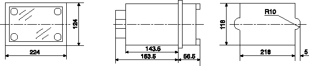
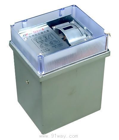
The relay is installed inside a metal casing with a transparent cover in front, embedded and mounted on a vertical panel.
The relay has an A22K structure, and its external dimensions, terminal diagram, and installation hole dimensions are shown in the attached figure
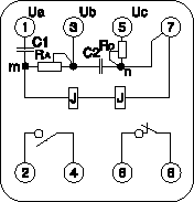
Figure 1 Internal wiring diagram
Technical data of DY-4 negative sequence voltage relay
3.1 Rated value: Line voltage 100, 173V, 50Hz.
3.2 Negative sequence action line voltage setting range: 6-12V, 10.4-20.8V.
3.3 The return coefficient shall not be less than 0.8.
When a symmetrical positive sequence 1.1 times the rated voltage is applied, the actuator of the relay should return to its original position.
3.5 Relays allow long-term application of 1.1 times the symmetrical positive sequence rated voltage.
3.6 The total power consumed by the relay at rated voltage shall not exceed 20VA.
When the voltage is not greater than 250V and the current is not greater than 2A, the breaking power of the contacts in a DC circuit with an inductive load and a time constant of 5 ˇŔ 0.75ms is 50W.
3.8 All circuits of the relay should undergo a test to withstand AC 50Hz, 2000V voltage, and a duration of 1 minute for the insulation of the casing.
The nominal values of the resistance and capacitance of the 3.9 filter, as well as the winding data of the actuator, are listed in Table 1.
|
Component symbols on the wiring diagram |
Component Name |
data |
|
RA |
resistor |
1380¦¸ |
|
Rc |
resistor |
920¦¸ |
|
XA |
capacitor |
4¦ĚF400V |
|
Xc |
capacitor |
2¦ĚF400V |
|
J |
Actuating element |
Each coil has 3000 turns of 0.18-QQ enameled wire |
4. Use and maintenance
4.1 Before using the relay, a mechanical inspection should be carried out, such as whether the screws and nuts are tightened, whether the movable system of the actuator rotates flexibly, and whether the balance spring and contact system work normally. Then, the relay action value is adjusted by changing the pointer position of the actuator, and the scale on the dial indicates the setting value of the negative sequence action line voltage. When testing with the method of simulating phase to phase short circuit, the operating voltage should be times the voltage of the negative sequence operating line. The simulation method is to short-circuit the two terminals of the simulated short circuit relay and apply a single-phase voltage between it and the non faulty phase terminal. At the same set point, the operating voltages for simulating phase to phase short circuits of AB, BC, and CA should be close to each other.
4.2 Negative sequence voltage filters and relays are already adjusted at the factory and generally do not require further adjustment. If it is found that the filter is unbalanced (there is a large unbalanced voltage at the output terminal when a symmetrical positive sequence voltage is applied), it can be adjusted according to the following regulations:
a. Adjust at rated frequency of 50Hz and when the voltage waveform is a sine wave;
b. Unscrew the terminal ˘ß screw and disconnect the connection circuit between the filter and the actuator. Apply a symmetrical positive sequence rated voltage to the input terminal of the filter, adjust the adjustable resistors R2 and R4, so that the minimum unbalanced voltage on the output terminal is not more than 1.5V at a rated voltage of 100V and not more than 2.6V at 173V. When measuring the unbalanced voltage, a vacuum tube voltmeter or a high internal resistance AC voltmeter should be used.
If it is difficult to apply symmetrical positive sequence voltage, single-phase voltage can also be added for adjustment. First, apply 100V AC voltage to the A and B phase terminals (˘Ů, ˘Ű), adjust R2 so that the voltage UC1 on capacitor C1 is 50V and the voltage URA on resistor RA is 86.6V; Then apply 100V AC voltage to the B and C terminals (˘Ű, ˘Ý), adjust R4 to make UC2=86.6V and URC=50V. High precision vacuum tube voltmeters or high internal resistance AC voltmeters should be used to measure voltage.
c. Tighten the terminal ˘ß screw to connect the output end of the filter and the coil of the actuator. If conditions permit, apply symmetrical positive sequence voltage and check the operation of the relay according to technical requirement 3.4.
When adjusting the actuator components, separate AC voltage adjustment should be applied to the coil winding, the reaction torque of the balance spring, and the stop screw to adjust its own operating voltage. The rated voltage is 100V ground, the minimum setting point is 10V, the maximum setting point is 20V, and the minimum setting point for 173V turns is 18V and the maximum setting point is 36V. The return coefficient is not less than 0.8. If necessary, the contact position can be adjusted appropriately, but it is necessary to ensure that the contact operates normally and reliably.
5 Ordering Instructions
When placing an order, please specify:
5.1 Product Model and Name
5.2 Order quantity.
5.3 Rated value.
attached figure
DY-4 type negative sequence voltage relay
HomeŁüQuality CommitmentŁüOrderingŁüPayment methodŁüproduct deliveryŁüsupportŁüDisclaimerŁüContact Us
Copyright®2011 www.91way.com Copyright.
PhoneŁş+86-21-66770508 +86-13916500500 FaxŁş+86-21-66108310
Email:91way@163.com Wechat:40606422
»¦ICP±¸2021005791şĹ ![]() »¦ą«Íř°˛±¸31010702003255şĹ
»¦ą«Íř°˛±¸31010702003255şĹ