
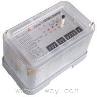
| Product nameŁş | JGL-10 series static overcurrent relay | ||||||
| specificationŁş |  |
||||||
| CategoryŁş | low-voltage electrical apparatus -- current relay | ||||||
| PriceŁş | factory price | ||||||
| BrandŁş | |||||||
| Place of OriginŁş | China | ||||||
| Available QuantityŁş | batch | ||||||
| delivery cycleŁş | Spot goods (or inquire by telephone) | ||||||
|
|||||||
JGL-10 series static inverse time overcurrent relay
I. Overview
1. JGL series static inverse time overcurrent relays (hereinafter referred to as relays) have inverse time characteristics and are used in relay protection devices for generators, transformers, and transmission and distribution systems. When the equipment is overloaded or short circuited, it can reliably operate within the predetermined time limit, send signals or cut off the faulty part.
2. This relay is an integrated circuit static relay that uses digital switches to set the current value, which is intuitive and convenient. Changing the setting value does not require inspection, and the setting range is 2-9.9A with a step difference of 0.1A. It has high accuracy, low power consumption, fast action time, and high return coefficient, making it an ideal replacement product for GL type overcurrent relays.
3. This relay complies with the power industry standard DL478-2001 "General Technical Conditions for Static Relay Protection and Safety Automatic Devices"; Mechanical industry standard JB3346-83 "Technical Conditions for Inverse Time Overcurrent Relays".
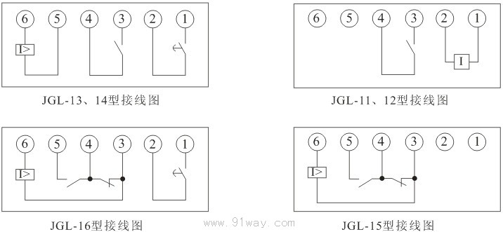
2ˇ˘ Classification and meaning of relay models
Comparison Table of JGL-10 Series Static Overcurrent Relay Models and Replaced Old Models:
3ˇ˘ Normal working environment
1. Environmental temperature: -10 ˇć to+50 ˇć;
2. Relative humidity: not exceeding 90%;
3. Atmospheric pressure: 86kPa~106kPa;
4. The usage location shall not experience vibrations exceeding the severity level 1 specified in GB/T14537.
5. Surrounding environment: Direct sunlight, rain, and water washing are not allowed. Non explosive media should not be present, and there should be no media or conductive media that can corrode metals, damage insulation and surface coatings. There should be no obvious water vapor or serious mold presence.
4ˇ˘ Main technical indicators
1. Rated value: 50Hz AC 5A, waveform distortion not exceeding 2%.
2. The overcurrent setting range is 2-9.9A (without auxiliary power supply), with a step difference of 0.1A, and the current setting value error is not greater than ˇŔ 3%.
3. The setting range of the speed multiple is 2-9.9 times, with a step difference of 0.1 times, and the error of the current speed setting value is not greater than ˇŔ 3%.
The quick action current of a relay is expressed as a multiple of the current setting value: Quick action current=Quick action multiple x Setting current.
4. Quick action time: At any set point of the relay, the action time at 1.2 times the quick action current shall not exceed 50ms.
5. Return coefficient: not less than 0.9.
6. Inverse time characteristic curve action equation:![]()
t: Inverse time action time K: Delay curve coefficient (setting range 0.1-9.9)
Is: Set current value I: Actual input current value (note: I/Is not greater than 1.2 is not recommended for use)
7. Time setting error of inverse time characteristic:
a) When I/Is<2, the average error is not greater than 10%;
b) When I/Is>2, the average error is not greater than 5%+30ms.
8. Typical inverse time characteristics are shown in the table below:
9. Power consumption: The power consumption at rated current shall not exceed 6VA.
10. Contact capacity
aˇ˘ Connection capacity: When the DC voltage does not exceed 250V, the continuous connection current of the structure type 1 product contacts is 10A;
bˇ˘ Breaking capacity: In inductive load circuits with a voltage not exceeding 250V (L/R=5ms), the breaking capacity of Structure 1 products is 50W.
cˇ˘ Overload capacity: The contacts of the relay can reliably disconnect a current of 1.5 times the specified capacity for 5 times, and the performance of the contacts still meets the requirements of technical standards.
11. Medium strength:
Under standard test atmospheric conditions, the conductive parts connected together should be able to withstand a test voltage of AC effective value 2000V/50Hz between the exposed non charged metal parts and the shell for 1 minute without insulation breakdown or flashover.
The same set of dynamic and static contacts should be able to withstand a test voltage of 1000V/50Hz AC effective value; After 1 minute, there was no insulation breakdown or flashover phenomenon.
Different sets of contacts should be able to withstand a test voltage of 2000V/50Hz AC effective value for 1 minute without insulation breakdown or flashover phenomenon.
12. Insulation resistance
Under standard test atmospheric conditions, the insulation value of the conductive parts of the relay between the exposed non charged metal parts and the outer shell should not be less than 20M ¦¸ when measured with an open circuit voltage of 500V using a testing instrument.
13. Working life: The relay operates 80000 times under the specified load, with an average time between failures of 80000 hours.
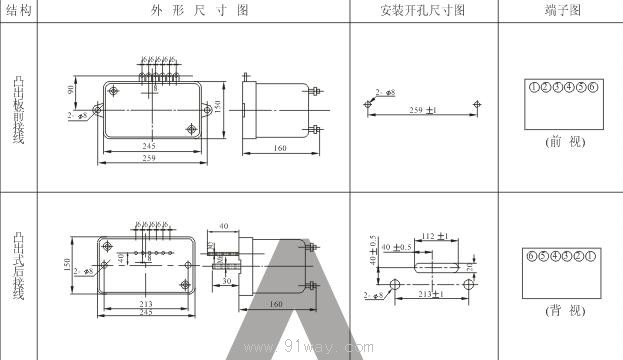
5ˇ˘ Installation and wiring instructions
1. To ensure the stability and reliable quality of the relay during use, it is necessary to conduct inspections and tests before use. The method is as follows:
aˇ˘ Remove the relay from the packaging box.
bˇ˘ Check whether the appearance of the relay is intact, whether there is condensation inside the shell, and whether the internal components are damaged.
cˇ˘ After confirming that the appearance of the relay is undamaged, various tests and power on inspections can be carried out.
dˇ˘ The inspection and testing content can be determined according to the actual situation, including setting value, delay time, insulation, withstand voltage, etc. The inspection method should follow JB3346-83 "Technical Conditions for Inverse Time Overcurrent Relays" and other relevant standards, as well as the technical indicators specified in the manual.
2. After the inspection and testing are completed, proceed with the installation according to the following steps.
aˇ˘ Firstly, familiarize yourself with the various wiring terminals of the relay, and then check if the installation dimensions match. bˇ˘ Connect the external wiring according to the usage requirements.
cˇ˘ After confirming that the wiring is correct, the circuit can be subjected to a power on test to check its functionality.
3. To ensure correct and reliable installation, a careful inspection should be conducted after installation. The inspection includes: whether the relay placement is balanced; Is there any damage to the casing; Are the screws and nuts loose; Whether the wiring is secure, etc. After confirming that everything is normal, it can be put into use.
6ˇ˘ Setting method and usage precautions.
1. Starting current setting: The starting current setting switch is the leftmost set of dip switches (two in total), with one on the left representing 1A level and one on the right representing 0.1A level. If its values are 5 and 6, then its setting value is 5.6A. Note that its range is 2-9.9A for products without auxiliary voltage, with a step difference of 0.1A.
2. K-value setting of inverse time characteristic curve: The K-value setting switch is the leftmost third group of dip switches (two in total), with the left one representing level 1; The one on the right represents level 0.1. The setting range of K value for this product is 0.1~9.9. For example, if its value is set to 5.0, the overcurrent action value is set to 5.0, and the actual input current is 30A, then its delay time is 13.5 seconds. However, its speed break multiple value should be set to 6 times or more. 3. Quick multiple setting: The quick multiple selection switch is the second group of left dip switches, with a range of 2-9.9 times. The left dip switch represents 1 times, and the right dip switch represents 0.1 times. When its value is 3 or 0, it is 3 times. If the current is set to 2.6A and the speed multiplier is 3 times, when the current reaches 3 ˇÁ 2.6=7.8, it will act directly without delay. Note that products without auxiliary power supply must be powered off before returning.
4. Precautions for use
aˇ˘ Attention should be paid to the testing method for products without auxiliary power supply: When using a transformer as a current source, it is required that the secondary turns of the transformer are equivalent to those of the current transformer. Otherwise, significant errors may occur due to impedance mismatch. When testing the speed of the quick action, if the current on-off method is used for measurement, the internal working power supply of the relay requires a certain establishment time, which will cause significant errors. However, during normal operation, the speed will be much faster due to the existence of the working power supply. Similarly, when measuring delay time using the on-off method, there may also be product errors.
bˇ˘ Action indication for products without auxiliary power supply: After the quick break and delay exits of the relay, the action indicator light on the relay panel will maintain the action record; After the relay action returns, the action indicator light needs to be manually reset.
7ˇ˘ Repair, maintenance, and storage
1. There are no special requirements for maintenance, that is, when the relay is not working properly or malfunctions, the staff will immediately replace it and send it to the factory for inspection.
2. Unused or spare relays should be stored in an environment with air circulation, temperature not exceeding+55 and not exceeding -25, and relative humidity not exceeding 90%. The warehouse should be free of acid, alkali, salt, corrosive or explosive gases, and should not be affected by dust, rain or snow.
8ˇ˘ Example of setting
Example: The parameters of the feed pump motor are known as: rated voltage VeD=6KV, capacity PeD=2000kw, rated current IeD=230A, starting factor=6, current transformer ratio LH=300/5, and motor starting time of 20S. (Two phase difference wiring)
Using JGL inverse time overcurrent relay to protect its overload and quick break, the setting calculation is as follows:
1. The starting current of the protective device relay is![]()
Explanation:
Kk - reliability coefficient, taken as 1.2 when the protection action is tripped or unloaded; The action signal is set to 1.05.
IeD - Rated current of electric motor.
Kjx - wiring coefficient of current transformer; If it is a three-phase complete star connection or a two-phase incomplete star connection, this value is 1. If it is a two phase difference wiring, Kjx=reflects the current during normal three-phase operation and three-phase short circuit; If Kjx=2 reflects the current when the current transformer is short circuited in two phases; If Kjx=1, it reflects the current when the other phase is short circuited with a current transformer.
Lh - Current Transformer Ratio
Kfh - is the return coefficient of the relay, generally taken as 0.9~1.
2. The speed determination value of the electric motor is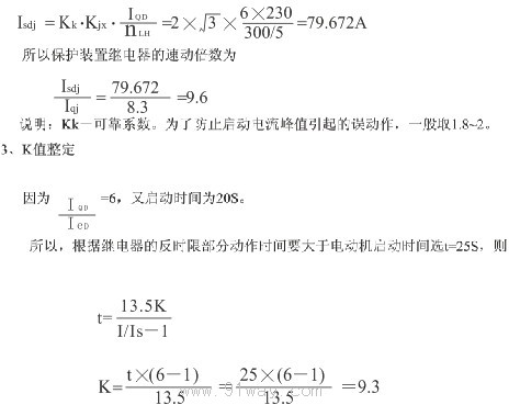
HomeŁüQuality CommitmentŁüOrderingŁüPayment methodŁüproduct deliveryŁüsupportŁüDisclaimerŁüContact Us
Copyright®2011 www.91way.com Copyright.
PhoneŁş+86-21-66770508 +86-13916500500 FaxŁş+86-21-66108310
Email:91way@163.com Wechat:40606422
»¦ICP±¸2021005791şĹ ![]() »¦ą«Íř°˛±¸31010702003255şĹ
»¦ą«Íř°˛±¸31010702003255şĹ