
| Product nameŁş | VSM800D Series Hall Voltage Sensor | ||||||
| specificationŁş |  |
||||||
| CategoryŁş | low-voltage electrical apparatus -- voltage sensor | ||||||
| PriceŁş | factory price | ||||||
| BrandŁş | |||||||
| Place of OriginŁş | China | ||||||
| Available QuantityŁş | batch | ||||||
| delivery cycleŁş | Spot goods (or inquire by telephone) | ||||||
|
|||||||
|
model |
VSM 050D |
VSM 100D |
VSM 200D |
VSM 300D |
VSM 400D |
VSM 500D |
VSM 800D |
||
|
VPN |
Primary rated input voltage |
ˇŔ50 |
ˇŔ100 |
ˇŔ200 |
ˇŔ300 |
ˇŔ400 |
ˇŔ500 |
ˇŔ800 |
V |
|
VP |
Measurement range of primary voltage |
0ˇ«ˇŔ100 |
0ˇ«ˇŔ200 |
0ˇ«ˇŔ400 |
0ˇ«ˇŔ600 |
0ˇ«ˇŔ800 |
0ˇ«ˇŔ1000 |
0ˇ«ˇŔ1000 |
V |
|
ISN |
Rated output current on the secondary side |
20ˇŔ1% |
mA | ||||||
|
KN |
turns ratio |
4000Łş1000 |
|||||||
|
RM |
measure resistance |
VC=ˇŔ15V 54ˇ«360 |
¦¸ | ||||||
|
VC |
power supply voltage |
ˇŔ12ˇ«ˇŔ15(ˇŔ5%) |
V | ||||||
|
Vd |
insulation voltage |
2.5KV effective value/50Hz/1 minute between the primary and secondary circuits |
|||||||
|
¦ĹL |
linearity |
<0.2 |
%FS | ||||||
|
X |
precision |
TA =25ˇć VC=ˇŔ15V ˇŔ0.8 |
% | ||||||
|
I0 |
Zero offset current |
TA =25ˇć <ˇŔ0.2 |
mA | ||||||
|
IOT |
Imbalance current temperature drift |
VP=0 TA =¨C25ˇ«+85ˇć <ˇŔ0.5 |
mA | ||||||
|
Tr |
response time |
<100 |
us | ||||||
|
TA |
Working environment temperature |
-25ˇ«+85 |
ˇć | ||||||
|
TS |
Storage environment temperature |
-40ˇ«+100 |
ˇć | ||||||
|
RS |
Internal resistance of secondary coil |
TA =85ˇć 50 |
¦¸ | ||||||
|
standard |
Q/3201CHGL02-2007 |
||||||||
Dimensions of VSM800D Series Hall Voltage Sensor (mm)
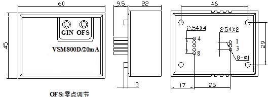
External wiring diagram
Instructions for Use
1. Incorrect wiring of sensors may result in module damage. After the sensor is powered on, the voltage to be measured is connected from the input end of the sensor, and the magnitude of the current can be measured at the output end.
2. Sensors with voltage output can be selected according to user needs. 3. The output amplitude of the sensor can be adjusted appropriately according to user needs.
HomeŁüQuality CommitmentŁüOrderingŁüPayment methodŁüproduct deliveryŁüsupportŁüDisclaimerŁüContact Us
Copyright®2011 www.91way.com Copyright.
PhoneŁş+86-21-66770508 +86-13916500500 FaxŁş+86-21-66108310
Email:91way@163.com Wechat:40606422
»¦ICP±¸2021005791şĹ ![]() »¦ą«Íř°˛±¸31010702003255şĹ
»¦ą«Íř°˛±¸31010702003255şĹ