
| Product nameŁş | VSM025A Hall Voltage Sensor | ||||||
| specificationŁş |  |
||||||
| CategoryŁş | low-voltage electrical apparatus -- voltage sensor | ||||||
| PriceŁş | factory price | ||||||
| BrandŁş | |||||||
| Place of OriginŁş | China | ||||||
| Available QuantityŁş | batch | ||||||
| delivery cycleŁş | Spot goods (or inquire by telephone) | ||||||
|
|||||||
|
model |
VSM025A |
|||
|
IPN |
Primary rated input current |
ten |
mA | |
|
IP |
Measurement range of primary current |
0ˇ«ˇŔ14 |
mA | |
|
ISN |
Rated output current on the secondary side |
twenty-five |
mA | |
|
KN |
turns ratio |
2500Łş1000 |
||
|
RM |
Measure resistance (VC=ˇŔ 12V) |
When IP=ˇŔ 10mA: 30-350 |
When IP=ˇŔ 14mA: 30-235 |
¦¸ |
|
(VC=ˇŔ15V) |
When IP=ˇŔ 10mA: 100-460 |
When IP=ˇŔ 14mA: 100~315 |
¦¸ | |
|
VC |
power supply voltage |
ˇŔ12ˇ«ˇŔ15(ˇŔ5%) |
V | |
|
IC |
current consumption |
VC=ˇŔ15V 10+Is |
mA | |
|
Vd |
insulation voltage |
2.5KV effective value/50Hz/1 minute between the primary and secondary circuits |
||
|
¦ĹL |
linearity |
<0.2 |
%FS | |
|
X |
precision |
TA =25ˇć VC=ˇŔ15V ˇŔ0.7 |
% | |
|
I0 |
Imbalance current |
TA =25ˇć <ˇŔ0.15 |
mA | |
|
IOT |
Imbalance current temperature drift |
IP=0 TA =-25ˇ«+85ˇć <ˇŔ0.35 |
mA | |
|
Tr |
response time |
90% of VPN ˇÜ40 |
¦Ěs | |
|
TA |
Working environment temperature |
-25ˇ«+85 |
ˇć | |
|
TS |
Storage environment temperature |
-40ˇ«+100 |
ˇć | |
|
Rp |
Internal resistance of primary coil |
TA =25ˇć 190 |
¦¸ | |
|
Rs |
Internal resistance of secondary coil |
TA =85ˇć 55 |
¦¸ | |
|
standard |
Q/3201CHGL02-2007 |
|||
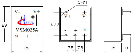
Dimensions (mm)
External wiring diagram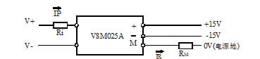
Instructions for Use
1. When measuring voltage, the Ri resistor is connected in series on the primary circuit of the sensor. To achieve optimal accuracy of the sensor, the size of Ri should be selected as much as possible to make the input current around 10mA.
2. Scope of work: Considering the internal resistance of the primary coil (compared to Ri, to maintain the temperature difference as low as possible) and isolation, this sensor is suitable for measuring voltages ranging from 10 to 500V. To ensure the stability of measuring resistance, the power of Ri should be at least 4 times the rated power (usually above 10W). 3. When soldering the sensor to the circuit board, a low-temperature soldering iron should be used, and the soldering time should be as short as possible, otherwise it may cause an open circuit in the internal wiring of the pins.
4. The socket position for installing sensors on the circuit board must be completely consistent with the pin size, and the pins should not be artificially squeezed, otherwise it may cause open circuits in the internal wiring of the pins.
HomeŁüQuality CommitmentŁüOrderingŁüPayment methodŁüproduct deliveryŁüsupportŁüDisclaimerŁüContact Us
Copyright®2011 www.91way.com Copyright.
PhoneŁş+86-21-66770508 +86-13916500500 FaxŁş+86-21-66108310
Email:91way@163.com Wechat:40606422
»¦ICP±¸2021005791şĹ ![]() »¦ą«Íř°˛±¸31010702003255şĹ
»¦ą«Íř°˛±¸31010702003255şĹ