
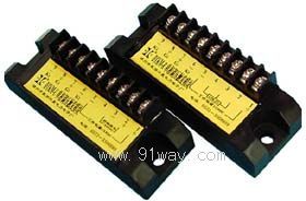
| Product nameŁş | GTCM-U,GTCM-R Solid state voltage regulation triggering module | ||||||
| specificationŁş |  |
||||||
| CategoryŁş | low-voltage electrical apparatus -- solid state relay | ||||||
| PriceŁş | factory price | ||||||
| BrandŁş | |||||||
| Place of OriginŁş | China | ||||||
| Available QuantityŁş | batch | ||||||
| delivery cycleŁş | Spot goods (or inquire by telephone) | ||||||
|
|||||||
| GTCM-U | GTCM-R | |
| Working power supply voltage | 14-18VDC, recommended 15VDC | 14-18VDC, recommended 15VDC |
| operating current | ˇÜ40mA | ˇÜ40mA |
| Adjustable signal | 0Ł10VDC | 10K ¦¸ adjustable resistor |
| Output pulse power | ˇÜ1W | ˇÜ1W |
| Output pulse time (width) | ˇÜ0.2ms | ˇÜ0.2ms |
| Operating Temperature | ˇÝ2000V | ˇÝ2000V |
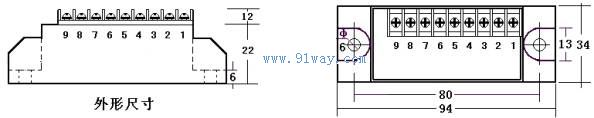
| External dimensions | 94ˇÁ25ˇÁ35 mm3 | 94ˇÁ25ˇÁ35 mm3 |
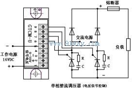
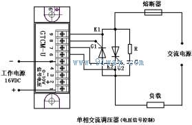
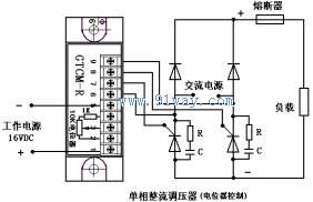
GTCM-U, GTCM-R solid-state voltage regulating trigger module external dimensions Installation wiring diagram: (unit: mm)
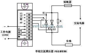
Notes:
Due to the low heat generated by the triggering module itself, it does not need to be installed on the heat sink.
The anode and cathode of the thyristor in the main circuit generally require the addition of a resistance capacitance absorption circuit for protection, with a resistance of 50-100 ¦¸/5W and a capacitance of 0.1-0.47uF/400VAC, or the use of a specialized overvoltage protection absorber produced by our factory.
When selecting thyristors and rectifiers in the main circuit, the current and voltage parameter values should be 2-4 times larger than the actual values.
The requirements for heat dissipation, cooling, and installation of thyristors and rectifiers in the main circuit can refer to relevant requirements.
HomeŁüQuality CommitmentŁüOrderingŁüPayment methodŁüproduct deliveryŁüsupportŁüDisclaimerŁüContact Us
Copyright®2011 www.91way.com Copyright.
PhoneŁş+86-21-66770508 +86-13916500500 FaxŁş+86-21-66108310
Email:91way@163.com Wechat:40606422
»¦ICP±¸2021005791şĹ ![]() »¦ą«Íř°˛±¸31010702003255şĹ
»¦ą«Íř°˛±¸31010702003255şĹ