SEK-F type panel fault indicatorDetailed product description:

1、 Product Introduction
The SEK-F panel fault indicator is a real-time monitoring device installed on the ring network switch, cable branch box, and box transformer in the distribution network system, used to indicate short circuits and single-phase grounding faults in corresponding cable sections. When a fault occurs in the line, the staff can use the alarm indication of the indicator to quickly determine the faulty section and locate the fault point. At the same time, the alarm information can be sent in real time to the server in the monitoring center, and the area and specific location of the fault can be displayed on the screen of the monitoring computer, guiding the line patrol personnel to quickly determine the fault section and find the fault point. This indicator provides the best way to solve the problem of fault finding. It is of great significance to improve work efficiency, shorten power outage time, quickly restore power supply, enhance power supply reliability and economic benefits.
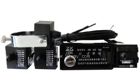
2、 The panel type fault detection device consists of two parts:
A、 Host B, short circuit (grounding) sensor
3、 Main functions of SEK-F panel fault indicator
1. Short circuit alarm indication: The short circuit sensor detects the current of the circuit during operation. When a short circuit fault occurs in the circuit and the fault current reaches or exceeds the alarm current setting value, the short circuit sensor sends an alarm signal, which is transmitted to the host through optical fiber. After the host receives this signal, it generates a corresponding alarm indication signal.
2. Grounding alarm indication: The grounding sensor detects the zero sequence current of the line during operation. When a grounding fault occurs in the line and the grounding fault current reaches or exceeds the alarm current setting value, the grounding sensor sends an alarm signal, which is transmitted to the host through optical fiber. After the host receives this signal, it generates a corresponding alarm indication signal.
3. Automatic reset: When the indicator sends an alarm signal, if there is no manual reset, the indicator will automatically reset within the set reset time.
4. Manual reset: When the indicator generates an alarm, it can be reset by triggering the "Reset/Test" button on the indicator host panel to release the alarm.
5. Testing: The indicator can perform self inspection of its working performance. Test by pressing and holding the "Reset/Test" button on the host panel for 1.5 seconds.
4、 Installation steps for SEK-F panel fault indicator:
1. The host of the indicator is installed on the front panel of the distribution cabinet;
2. Installation of short-circuit sensors;
The short-circuit sensor must be installed on the single-phase branch of the cable, and can be directly installed on the tested cable and fastened to prevent sliding and detachment.
3. Installation of grounding sensor:
When installing the grounding sensor, attention should be paid to surrounding the three wires of the cable. The grounding wire of the cable must be threaded back through the sensor and fastened to prevent sliding and detachment.
4. Connection:
The sensor and the host are connected by fiber optic cables. During installation, the two ends of the fiber optic cable are inserted into the fiber optic connectors of the sensor and the host respectively, and the connectors are tightened to prevent the fiber optic cable from being pulled out. The specific steps are as follows:
4.1. Insert the other end of the A-phase short-circuit sensor fiber optic cable into the corresponding fiber hole A on the rear panel of the host;
4.2. Insert the other end of the B-phase short-circuit sensor fiber optic cable into the corresponding fiber hole on the back panel of the host;
4.3. Insert the other end of the C-phase short-circuit sensor fiber optic cable into the corresponding fiber hole on the rear panel of the host;
4.4. During installation, insert the other end of the grounding sensor fiber optic cable into the corresponding fiber optic hole D on the rear panel of the host
5、 Host size: length x width x height: 96 x 49 x 85mm
Host installation opening size: Length: 91 ± 0.5mm Width: 43 ± 0.5mm
6、 Operation:
1. Test: When a self-test is required, press the "Reset/Test" button on the panel and hold it for 1.5 seconds. The machine will enter self-test mode and all items on the panel will be checked
The indicator light flashes, indicating that the whole machine is working normally. The entire process will automatically end after 7 seconds, or pressing the "Reset/Test" button again can end the self-test process and restore normal status.
2. Clear alarm: When a fault occurs in the circuit, the indicator generates an alarm signal. After the fault is resolved, the alarm should be cleared. The alarm can be released by triggering the "Reset/Test" button on the indicator host panel. If there is no manual reset, the indicator can automatically reset after the set time (6, 12, 24, 48 hours).
7、 Set reset time:
There are four types of indicator alarm status clearing time: 6h, 12h, 24h, 48h. When adjusting the reset time, the front panel of the host needs to be turned on, and the dip switch needs to be adjusted. When the first position of the switch is set to NO and the other three groups are set to OFF, the reset time is 6 hours, and so on. The factory setting value is 12 hours.
8、 Technical parameters
1. Short circuit current alarm: ≥ 150A with an error of ± 10%; The factory setting is 800A, with a short circuit delay of 60mS
2. Grounding current alarm: 3A~200A error ± 10%, factory set to 10A, grounding delay 40mS
3. Working power supply: ER14505 3.6V lithium battery (with a service life of not less than 5 years)
4. Standby current of the whole machine: ≤ 5 μ A
5. Automatic reset time: can be set as needed
6. Indicator protection level: host IP40; Sensor IP65
7. Maximum withstand current of short-circuit current sensor: 20KA 4S
8. Working environment: -35 ℃ to+65 ℃; Relative temperature: ≤ 95%; Waterproof, acid resistant, salt spray resistant
9. Scope of use: In systems below 20kV level
 Related Products:
- Related articles:

