The NJ type contact wedge block backstop is a new type of backstop device used for belt conveyors. It is directly installed on the transmission drum shaft extension or the low-speed shaft extension of the reducer, and has strong anti reverse ability, allowing the maximum torsional rejection to usually reach hundreds of thousands of Newton meters or more. When a large belt conveyor loaded with materials suddenly stops running due to various reasons, the NJ type backstop can effectively prevent reverse sliding accidents caused by material gravity; And in the reverse state, the entire drive device is still in the unloaded state, which not only does not affect the maintenance and replacement of drive components such as motors and reducers, but also makes it safer and more reliable to prevent reverse accidents caused by damage to the drive system. Therefore, it is an ideal anti reverse safety protection device for large belt conveyors.
Model meaning
For example, the code NJ16-S-140 represents the NJ type contact type backstop, with a rated backstop torque of 16000N. m, the inner ring rotates clockwise, and the installation hole diameter is 140mm.
Structure and Working Principle
The wedge block, inner ring, and outer ring are the basic anti stop components of the wedge block anti stop, among which the wedge block (Figure 1) is the key part of the anti stop. The wedge block anti stop utilizes the unique cross-sectional shape of the wedge block, as well as its special geometric and mechanical relationships with the inner and outer rings, to achieve one-way braking.
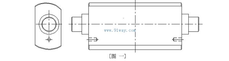
In the manufacturing process of the backstop, advanced alloy steel materials are strictly selected for the basic backstop components, which are precision machined and rigorously heat-treated to ensure accurate backstop action, strong load-bearing capacity, easy release, and safe and reliable performance. The wedge block of the backstop is installed in the cage, and a certain number of rollers are arranged between the wedge blocks to form a wedge block device component (Figure 2). The rollers are used to maintain the concentricity of the inner and outer rings, while bearing radial loads. The structure is very compact.

The wedge assembly component is installed in the raceway formed by the inner and outer rings. When the backstop rotates freely, the roller will rotate with its own axis and drive the cage and wedge to revolve along the inner and outer rings. On the one hand, it evenly spreads lubricating oil (grease) in the raceway, improving the lubrication effect; On the other hand, it constantly changes the contact position between the wedge block and the inner and outer rings to ensure the reliable performance of the backstop during long-term use.
Technical characteristics and installation dimensions
Table 1 Main parameters of NJ type backstop
| Specification |
Maximum reverse torque N · m |
Maximum speed of inner circle r/min |
Idle resistance torque N · m |
Maximum aperture mm |
Maximum mass kg |
| NJ25 |
25000 |
100 |
35 |
160 |
112 |
| NJ38 |
38000 |
100 |
45 |
200 |
183 |
| NJ50 |
50000 |
80 |
75 |
220 |
355 |
| NJ90 |
90000 |
50 |
95 |
250 |
644 |
| NJ125 |
125000 |
50 |
100 |
270 |
755 |
| NJ180 |
180000 |
50 |
110 |
300 |
1088 |
| NJ270 |
270000 |
50 |
140 |
320 |
1426 |
| NJ320 |
320000 |
50 |
160 |
350 |
1921 |
| NJ520 |
520000 |
50 |
220 |
420 |
2945 |
| NJ700 |
700000 |
50 |
250 |
450 |
3518 |
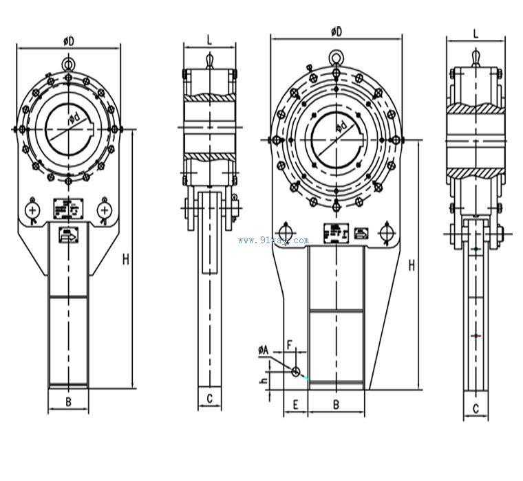
NJ25-NJ90 contact type backstop NJ125-NJ170 contact type backstop
Table 2 Installation dimensions of NJ type backstop
| Specification |
Structural dimensions (mm) |
| d |
A |
B |
C |
D |
E |
F |
H |
h |
L |
| NJ25 |
120-160 |
—- |
140 |
80 |
360 |
—- |
—- |
800 |
—- |
180 |
| NJ38 |
160-200 |
—- |
160 |
88 |
430 |
—- |
—- |
850 |
—- |
210 |
| NJ50 |
160-220 |
—- |
200 |
100 |
500 |
—- |
—- |
1000 |
—- |
240 |
| NJ90 |
180-250 |
—- |
250 |
120 |
600 |
—- |
—- |
1200 |
—- |
290 |
| NJ125 |
200-270 |
40 |
280 |
120 |
650 |
120 |
60 |
1100 |
80 |
290 |
| NJ180 |
230-300 |
45 |
320 |
130 |
780 |
135 |
60 |
1300 |
80 |
320 |
| NJ270 |
250-320 |
50 |
360 |
140 |
850 |
150 |
70 |
1500 |
100 |
340 |
| NJ320 |
250-350 |
55 |
400 |
140 |
930 |
160 |
70 |
1600 |
100 |
360 |
| NJ520 |
320-420 |
60 |
450 |
150 |
1030 |
180 |
80 |
1800 |
120 |
450 |
| NJ700 |
350-450 |
70 |
500 |
160 |
1090 |
210 |
100 |
2000 |
120 |
480 |
Table 3 Diameter range of installation holes for NJ type backstop
| Specification |
Installation aperture range mm |
Preferred installation hole diameter mm |
| NJ25 |
120-160 |
120,130,140,150,160 |
| NJ38 |
160-200 |
160,170,180,190,200 |
| NJ50 |
160-220 |
160,170,180,190,200,210,220 |
| NJ90 |
180-250 |
180,190,200,210,220,230,230,240,250 |
| NJ125 |
200-270 |
200,210,220,230,240,250,260,270 |
| NJ180 |
230-300 |
230,240,250,260,270,280,290,300 |
| NJ270 |
250-320 |
250,260,270,280,290,300,320 |
| NJ320 |
250-350 |
250,260,270,280,290,300,320,340,350 |
| NJ520 |
320-420 |
320,340,350,380,400,420 |
| NJ700 |
350-450 |
350,380,400,420,450 |
Within a certain range, each specification of backstop has several different installation hole diameters for users to choose from. The range of installation hole diameters and the available preferred installation hole diameters are shown in Table 3. Unless otherwise specified by the user, the installation hole size and dimensional accuracy shall be supplied according to the user's requirements.
The installation hole of the backstop adopts a flat key form, and the keyway size is provided according to GB1095-79 standard.
Installation of backstop
Before installation, it should be checked whether the operating speed of the shaft where the backstop is installed is within the maximum speed range allowed by the backstop;
Due to the fact that the inner ring of the backstop can only rotate in one direction, the direction of rotation is indicated by the arrow on the steering indicator on the outer shell. Before installation, it is necessary to check whether the rotation direction of the shaft is consistent with the rotation direction of the inner ring of the backstop;
When installing the backstop, only apply pressure to the inner ring of the backstop. To avoid damaging the inner ring end, please use a wooden hammer to strike. Do not knock on the outer shell, sealing sleeve, dust cover and other parts of the backstop;
When assembling the backstop with the shaft, only flat keys can be used and wedge keys are not allowed.
⑸ For the check valve with thin oil lubrication, one of the four oil injection holes should be located at the bottom of the housing for future maintenance (refer to Figure 4);

After installation, press the inner ring of the backstop with an end cap at the end of the shaft;
The lower end of the anti rotation arm of the backstop should be fixed between two blocking irons, and it should be ensured that the backstop can move freely in the axial direction. There should be a gap of 5-10mm between the blocking iron and the force arm;
The anti rotation arm of the backstop should be installed vertically as much as possible, and can also be installed in a tilted or horizontal manner;
All shaft end cover plates, stoppers, etc. are not included in the supply scope of the backstop and are to be resolved by the user themselves.
Controlled by controls
Wedges, rollers, retainers, inner wheels, outer wheels.
vulnerable parts
Skeleton oil seal, rubber strip, bearing.
Lubrication and maintenance
⑴ The lubrication of NJ type contact wedge block backstop adopts thin oil lubrication, using No. 40 mechanical lubricating oil. The product is not equipped with lubricating oil at the factory and must be refilled before use;
There are four holes on the outer shell of the check valve for oil injection, oil level inspection, and oil discharge (see Figure 4). Remove the hole plug to inject oil and check the oil level, inject oil from the top until it overflows from the oil level, and then tighten the hole plug;
After the first 24 hours of operation, drain all the oil, clean the internal cavity of the check valve with clean oil, and then inject clean lubricating oil that meets the requirements.
After running the check valve for one month, drain all the oil and replace all the engine oil. Then, add some new oil every three months and replace all the engine oil every six months.
After one year of operation, the backstop should be disassembled, cleaned, and checked for any detachment or damage to the spring, as well as the integrity of the wedge, inner ring, outer ring, and rollers. If there are any defects, they should be replaced immediately.
Regularly check the fastening bolts of the anti rotation arm and anti transposition to ensure effective fastening.
Safety Warning and Precautions
When installing the backstop, pay attention to the rotation direction of the rotating label. The direction of rotation of the label should be consistent with the direction of operation of the backstop. Lubricating oil (grease) containing molybdenum disulfide, graphite, or any extreme pressure additive that improves lubrication performance cannot be used. These additives can reduce the coefficient of meshing friction and may cause the backstop to slip.
Fault analysis and troubleshooting
| Fault phenomenon |
Cause analysis |
Exclusion method |
| The backstop does not work |
The direction of rotation towards the label is reversed or the installation of the reverse stopper is reversed |
Reverse the installation of the backstop |
| The check valve has leakage phenomenon |
Hydraulic components are not tightly sealed, or the seals are deformed due to compression |
Re tighten or replace the seal |
| Abnormal operation of the backstop |
The oil is too dirty |
Filter or replace working oil |



 Zoom in on the image
 Related Products:
 NF type non-contact backstop
  沪公网安备31010702003255号
 Your location:




