
| Product nameŁş | SGP-1 type high-frequency relay | ||||||
| specificationŁş |  |
||||||
| CategoryŁş | low-voltage electrical apparatus -- Frequency relay | ||||||
| PriceŁş | factory price | ||||||
| BrandŁş | |||||||
| Place of OriginŁş | China | ||||||
| Available QuantityŁş | batch | ||||||
| delivery cycleŁş | Spot goods (or inquire by telephone) | ||||||
|
|||||||
1 Purpose
SGP-1 high-frequency relay is used in the secondary relay protection lines of high-frequency cutting machines in hydropower plants and power systems, as a sensitive component to respond to frequency increases.
2 Structure and working principle
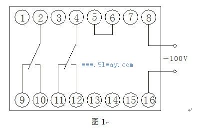
2.1 The relay adopts JK-2 plug-in housing. The appearance and installation hole size are shown in the appendix, and the back terminal diagram is shown in Figure 1.
2.2 Working principle
This relay is based on T=1/f, and the frequency is reflected by the length of the cycle. The measured AC sine wave is converted into a square wave by an inverter, and the differential circuit converts the square wave into a counting zero spike pulse. The period of the spike pulse is the period of the measured frequency. With the help of a quartz crystal oscillator, a counter is used to calculate how many crystal oscillator cycles there are in a measured cycle. The frequency of this standard cycle is used to set the relay to operate. The following is the description.
Technical requirements for SGP-1 high-frequency relay
3.1 Rated data
Rated voltage 100V; rated frequency 50Hz.
3.2 Range of Action Frequency Setting
50.05~66Hz frequency, allowed to exit above 50.4Hz.
3.3 Return frequency
At rated voltage, the difference between the operating frequency and the return frequency shall not exceed 0.01Hz.
3.4 Voltage Influence
When the measured voltage varies within the range of 60-120V, the difference in operating frequency should not exceed 0.015Hz.
3.5 Action time setting range
The range of action time setting is divided into three types: 0.15~1.5S, 0.3~5S, and 2~20S.
3.6 The return time shall not exceed 70ms.
3.7 Environmental temperature impact
When the ambient temperature varies within the range of -10~+50 ˇć, the change in operating frequency shall not exceed 0.025Hz.
3.8 Power consumption
Not exceeding 2.5VA at rated voltage.
3.9 Contact Capacity and Contact Form
In a DC inductive load circuit with a voltage not exceeding 220V and a current not exceeding 0.5A (circuit time constant of 5ms ˇŔ 15%), 30W can be disconnected. The contact form is two conversions.
3.10 Electrical lifespan
The relay can withstand 5000 actions and still function normally after that.
3.11 Weight
The weight of the relay is about 1.2kg.
4 Debugging Methods
The frequency signal waveform used for debugging is a sine wave, without visible waveform distortion. When using the instrument, accuracy should be considered.
4.1 General Debugging
Set the dial switch to a low frequency value according to the frequency setting method. When changing the measured frequency, the relay should act. Change the setting value of the dial switch, adjust the measured frequency, and the relay should operate at the set point. When the scale is in error, the variable capacitor C7 can be adjusted to operate at the corresponding frequency value, and the frequency setting corresponds to the N number of dial switches (last three digits). If the set frequency is greater than 62.5Hz.
4.2 Low voltage lockout
Low voltage lockout debugging can adjust potentiometer R27. The method is to adjust the measured voltage to 57V, with the measured frequency near the operating frequency, causing the relay to move from operating to non operating, and then increase the voltage at this frequency point, causing the relay to operate. Repeat this process several times to obtain a lockout voltage of 57V.
4.3 Time Debugging
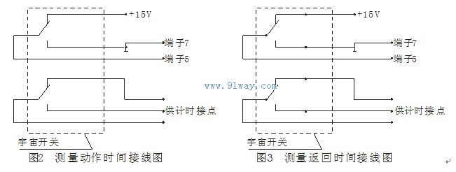
Action time: Open the terminal 5 connector of the base and connect the wires to the terminal as shown in Figure 2. Make the action time consistent with the nameplate data.
Return time: Open the connection piece of terminal 5 on the base and wire the terminal as shown in Figure 3. The return time is 70ms.
4.4 Test circuit debugging
When debugging, as long as the switch is placed in the test position according to the nameplate, the relay will operate within the operating range (but not exit).
HomeŁüQuality CommitmentŁüOrderingŁüPayment methodŁüproduct deliveryŁüsupportŁüDisclaimerŁüContact Us
Copyright®2011 www.91way.com Copyright.
PhoneŁş+86-21-66770508 +86-13916500500 FaxŁş+86-21-66108310
Email:91way@163.com Wechat:40606422
»¦ICP±¸2021005791şĹ ![]() »¦ą«Íř°˛±¸31010702003255şĹ
»¦ą«Íř°˛±¸31010702003255şĹ