
| Product nameŁş | SQP-6 type underfrequency relay | ||||||
| specificationŁş |  |
||||||
| CategoryŁş | low-voltage electrical apparatus -- Frequency relay | ||||||
| PriceŁş | factory price | ||||||
| BrandŁş | |||||||
| Place of OriginŁş | China | ||||||
| Available QuantityŁş | batch | ||||||
| delivery cycleŁş | Spot goods (or inquire by telephone) | ||||||
|
|||||||
Application of SQP-6 Underfrequency Relay
a. Automatically cut off some user loads according to the grid frequency;
b. Automatically disconnect according to frequency in interconnected systems;
c. To ensure the safety of large steam turbine generators or to ensure power supply to important users, disconnect the generator units from the system when the grid frequency decreases;
d. Used in other industrial sectors for power frequency control.
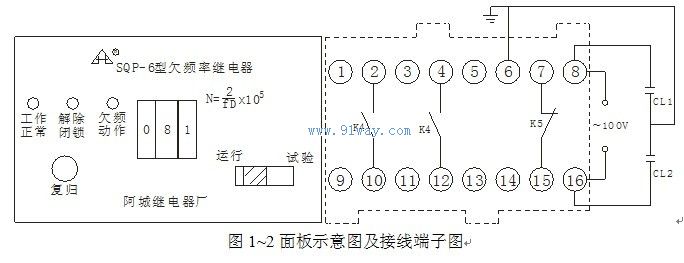
2 Structure and Working Principle
The relay adopts JK-2 housing, and the external dimensions, rear terminals, and installation hole diagram are shown in the appendix. The schematic diagram of the panel is shown in Figure 1. The wiring terminal diagram is shown in Figure 2.
Technical Requirements for SQP-6 Underfrequency Relay
1. The rated value is 100V, 50Hz.
2. The frequency setting error shall not exceed ˇŔ 0.0125Hz.
3. The frequency setting range is 45~49.5Hz, and the minimum frequency setting level difference is 0.0125Hz.
4. The return coefficient of underfrequency action shall not exceed 1.002, and the maximum return time shall not exceed 60ms.
5. It is equipped with a normal operation (monitoring) level. When the grid frequency is below 51Hz and the main circuit inside the relay is normal, the normal operation level indicator light will emit a display; If there is a fault in the main circuit inside the relay, the indicator light will turn off (see the previous description of the working principle for the main circuit of the relay).
6. There are two levels of unlocking, the first level is 49.5Hz and the second level is 49.26Hz. When the grid frequency is lower than the selected frequency setting of the unlocking level, the unlocking indicator light will turn on, indicating that the relay underfrequency action circuit is allowed to operate; When the grid frequency is higher than the frequency value selected by the blocking level, the light goes out, indicating that the outlet of the underfrequency action circuit is blocked, preventing the relay from misoperation caused by faults such as transistor breakdown at the outlet due to underfrequency action when the grid frequency is normal.
7. There is a slip locking circuit, and its setting formula is df/dt=K (Hz/s). In the formula, df is the difference between the frequency setting values of the unlocking stage and the underfrequency action stage, and dt has eight levels, namely 0.01, 0.02, 0.04, 0.08, 0.1, 0.2, 0.4, 0.8. dt uses a pulse counting circuit, and K (Hz/s) is selected according to the power grid situation.
8. There is an underfrequency action level, and the underfrequency action frequency setting formula is N=2/fD ˇÁ 100000. In the formula, fD is the setting frequency, N is the setting value of the finger wheel switch, and a three position finger wheel switch is used for setting. There are two sets of contacts for the 220V DC circuit in the underfrequency action, each with a capacity of 30W.
9. The underfrequency action circuit has a delay, and its delay part adopts a pulse counting circuit. The delay (t) is set to nine levels, which are 0.08, 0.1, 0.15, 0.2, 0.3, 0.5, 15, 20, and 25 seconds respectively. Users can choose according to their needs through the switch.
10. The working range of the input voltage of the relay is AC 60-120V, and below 60V (about 55V), it automatically performs low voltage lockout.
11. Under rated voltage, when the ambient temperature changes within the range of -10~50 ˇć, the difference between the operating frequency value of any set point of the relay and the operating frequency value under reference conditions shall not exceed ˇŔ 0.025Hz.
12. The relay is equipped with 6, 12, and 24V DC stabilized power supplies, which are obtained by rectifying and stabilizing the input voltage signal. Normal power consumption is not greater than 3.5VA, no additional power supply is required.
13. There is a low-frequency test signal inside, and the relay can be manually switched on and off for transmission testing during operation. Before the experiment, disconnect the screen and trip the circuit pressure plate to prevent accidental load switching.
14. The relay is equipped with a central signal contact, with a contact capacity of 220V DC and 30W DC. When there is a fault in the main circuit of the relay, a fault in the under frequency action circuit, or a slip locking situation, an alarm can be triggered through the central signal contact.
15. Not affected by high-order harmonics in the power grid.
16. When the high-frequency interference relay is in the critical state of operation, all input and output circuits should be tested for common state interference using 2.5kV high-frequency oscillation waves, and the AC input circuit should be tested for sulfonic state interference using 1kV high-frequency attenuated oscillation waves, and should not be operated incorrectly or refused to operate.
SQP-6 type underfrequency relay
HomeŁüQuality CommitmentŁüOrderingŁüPayment methodŁüproduct deliveryŁüsupportŁüDisclaimerŁüContact Us
Copyright®2011 www.91way.com Copyright.
PhoneŁş+86-21-66770508 +86-13916500500 FaxŁş+86-21-66108310
Email:91way@163.com Wechat:40606422
»¦ICP±¸2021005791şĹ ![]() »¦ą«Íř°˛±¸31010702003255şĹ
»¦ą«Íř°˛±¸31010702003255şĹ