
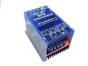
| Product name: | JSC series single-phase half air bridge thyristor DC speed regulation device | ||||||
| specification: |  |
||||||
| Category: | motor products -- DC speed regulator | ||||||
| Price: | factory price | ||||||
| Brand: | |||||||
| Place of Origin: | China | ||||||
| Available Quantity: | batch | ||||||
| delivery cycle: | Spot goods (or inquire by telephone) | ||||||
|
|||||||
Product Overview
1: Device parameters
1: Input voltage: single-phase AC 220V or three-phase AC 380V+10%
2: Output voltage: DC armature 0-110V or 0-220V or 440V
Excitation 110V or 198V
3: Rated output current: armature 25A 50A
Equipped motor: less than 7.5KW
(For DC motor speed controllers greater than 7.5KW, please refer to the KSG611 series)
4: Output excitation current: 2A, 5A (10A, 20A...)
5: Speed range: 1:30
6: Static error rate:<5%
7: Locking current setting value: 1.3 times the rated current
8: Can achieve analog signal input, synchronize multiple motors, and connect with PLC
2: Purpose: JSC series single-phase half air bridge thyristor DC speed regulation device, suitable for armature power supply of various DC electric motors with a power of less than 7.5KW, to achieve constant torque stepless speed regulation of DC motors. By using this device to supply power to a DC motor, the motor can start and accelerate quickly and smoothly, with minimal dynamic speed drop and short recovery time for sudden loads. Suitable for mechanical transmission with a wide speed range and high stability accuracy, such as light industry machinery, plastic machinery, printing machinery, papermaking machinery, food packaging machinery and other industrial sectors. As a sub drive for small and medium-sized DC motors, it plays a role in speed regulation and stability. This device is also suitable for situations where the motor starts at full load and full voltage.
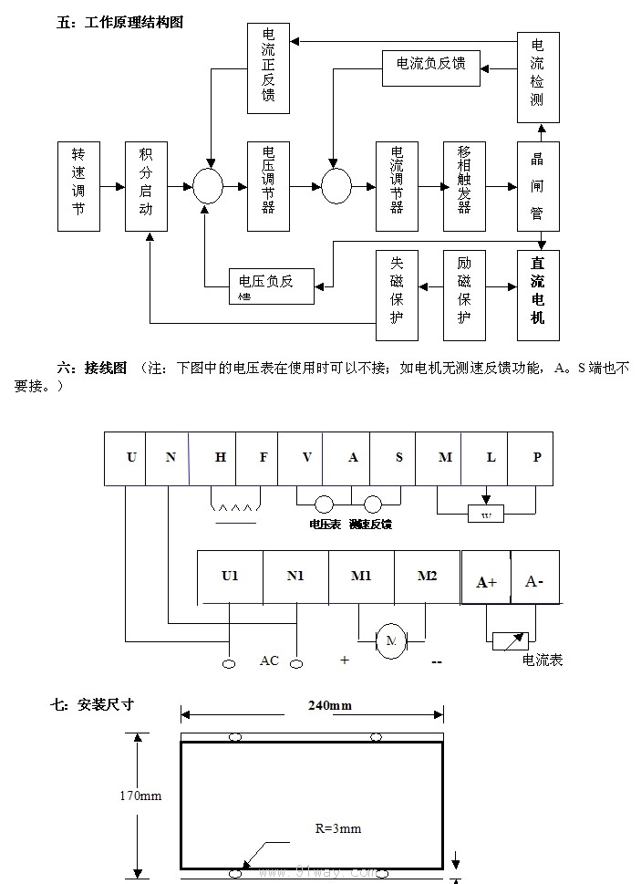
3: Working principle
The JSC series single-phase half air bridge thyristor DC speed regulation device consists of integral starting, voltage regulator, current regulator, phase-shifting trigger, thyristor rectifier, current sampling amplification, overcurrent indication, demagnetization protection and other circuits.
1: Integral starting is composed of N4/2, C22, RP3, etc. When a sudden control voltage input is applied, the output of N4/2 rises in an integral state, thereby achieving flexible starting, reducing acceleration and overshoot, making each start smoothly rise, and preventing strength shocks in mechanical transmission. Adjusting RP3 can change the integral start time, and the adjustment range of this device is 2-10 seconds.
2: The voltage regulator and current regulator both use high-performance PI type regulators, whose comprehensive effect ensures the stability and speed of the device reach the optimal state.
The voltage regulator consists of N4/3, C16, R46, etc. Its input terminal has a given voltage, negative feedback voltage, and current positive feedback voltage superimposed. When the power supply voltage and load fluctuate, the output voltage should be automatically adjusted in a timely manner to maintain stable motor speed. Adjust RP1 to correct the mechanical hardness of the motor, and adjust RP4 to stabilize the maximum output voltage of the device.
The current regulator is composed of N4/4, C14, R38, D23, etc. Due to the introduction of negative current feedback, when the load increases and exceeds the steady current, the output voltage steadily decreases, and the output current no longer rises; When the motor is stuck, the output current remains stable within the rated current range, effectively protecting the device and the DC motor. Due to the current regulator stabilizing the maximum output current, the current is also controlled within the rated current during full load and full voltage starting of the motor, allowing the motor to start quickly and smoothly. Adjusting RP2 can change the maximum stabilization current.
3: N4/1, R61, R64, R65, R70 and other components form a current sampling amplification circuit, providing control voltage for current regulators and voltage regulators. RP5 is a potentiometer for adjusting the tachometer.
4: N3 is a dedicated phase-shifting trigger integrated circuit, which has the advantages of wide phase-shifting range and stable output pulse. D17 is a pulse power amplifier. Drive the thyristor rectifier with sufficient power.
5: N2/1 and N2/2 are fast mode thyristor rectifiers, R16, For the absorption of AC input overvoltage by varistors, R17 is for DC output overvoltage absorption, R11, R12, C7, C8 are for thyristor switch resistance capacitance absorption. The above circuit serves as an overvoltage protection for thyristors and diodes.
6: D1-D7 are excitation power supplies, D8 are magnetic field connection indicators, N1, R2, R4, R3 are demagnetization protection circuits. When the motor excitation power supply is disconnected, N1 outputs negative voltage, cutting off the supply and constant voltage, causing the output DC voltage to drop to 0, preventing the DC motor from runaway during demagnetization, thus protecting the motor and the device.
7: D26 is for power on display, D30 is for overcurrent display. D8 is the excitation connection display.
4: Main advantages 1: Wide speed range, high precision, sensitive protection action, reasonable structure, can be used for synchronous speed regulation of multiple motors.
8: Please pay attention to the following situations when using:
1: Carefully check and verify the wiring according to the instructions to avoid any errors and damage to the device.
2: During machine operation, it is prohibited to use metal objects to come into contact with the internal components of the device.
3: The potentiometers on the control board are adjusted correctly at the factory and should not be easily adjusted.
4: Professional personnel should be hired for repairs to prevent the scope of the malfunction from expanding.
5: When using an oscilloscope for inspection, please pay attention to the power plug of the oscilloscope and do not add a grounding wire.
6: The resistance value of the potentiometer with a given speed can range from 4.7K to 10K.
Comparison Table of Main Technical Parameters for DC Speed Governor Selection:
| model | AC input voltage | DC output voltage | output current | excitation voltage | current | Capable of matching motor power | Appearance | |
| DC-51 |
AC 220V |
DC0-24V | 1.5A | DC24V | 0.5A | 120W | 55*90*80 | Panel installation |
| DC-51 | DC0-90V | 1A | DC90V | 90W | ||||
| DC-51 | DC0-180V | DC180V | ||||||
| KZT-01 | DC0-180V | 2A | DC198V | 1A | 100W | 132*125*65 | desktop
Install | |
| KZT-04 | 3A | 1A | 400W | 150*130*80 | ||||
| ZKS-I | AC
220V |
DC0-180V | 5A | DC198V | 2A | 550W | 150*160*80 | Panel installation |
| ZKS-II | 10A | 1.1KW | 260*160*80 | |||||
| ZKS-III | 20A | 2.2KW | 320*170*80 | |||||
| JSC-601 series | AC
two hundred and twenty |
0-180V | 10A
20A 50A |
180V-200V | 2A | 1.5KW
3.0KW 5.5KW |
240*170*135 | Wall mounted installation |
| JSC601A | AC
380V |
0-260V | 50A | 180-200V | 2A | 7.5KW | ||
| JSC611 | 0-440V | 30A
60A 100A |
180-200V | 5A | 11KW
22KW 40KW |
380*280*150 |
Home|Quality Commitment|Ordering|Payment method|product delivery|support|Disclaimer|Contact Us
Copyright®2011 www.91way.com Copyright.
Phone:+86-21-66770508 +86-13916500500 Fax:+86-21-66108310
Email:91way@163.com Wechat:40606422
沪ICP备2021005791号 ![]() 沪公网安备31010702003255号
沪公网安备31010702003255号