|
Product name: |
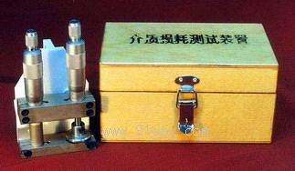
S914 Q Dielectric loss testing device (matching with Q meter)
|
|
specification: |
|

 Zoom in on the image Zoom in on the image |
|
Category: |
instrumentation and meters
-- Q meter |
|
Price: |
factory price |
|
Brand: |
|
|
Place of Origin: |
China |
|
Available Quantity: |
batch |
|
delivery cycle: |
Spot goods (or inquire by telephone) |
|
| |
Shanghai Beiyuan Industry and Trade Co.,Ltd
+86-21-66770508
+86-13901609058 |
 91way@163.com 91way@163.com
 13901609058(Wechat) 13901609058(Wechat)
|
|
|
|
S914 Q Dielectric loss testing device (matching with Q meter)Detailed product description:

One Overview
The S914 dielectric loss testing device box AS2851 Q meter (or other similar Q meters) is used to test the high-frequency dielectric loss tangent and dielectric constant of insulation materials.
II Working characteristics of the S94 dielectric loss testing device (Q meter matching)
1. Flat capacitor: Pole size: φ 25.4mm, adjustable range and resolution of pole spacing: ≥ 10mm ± 0.01mm,
2. Cylindrical capacitor: Linear capacitance: 0.33pF/mm ± 0.05 pF, adjustable length range and resolution: ≥ 0-20mm ± 0.01mm
3. Fixture plug spacing: ≤ 4 × 10⁻⁴
III Working principle of S94 dielectric loss testing device (Q meter matching)
This testing device consists of two micro capacitors. The flat capacitor is generally used to hold the tested sample, while the cylindrical capacitor is a linear variable capacitor with a resolution of up to 0.0033pF. It is equipped with a Q-meter as an indicator instrument. The loss tangent value of the insulation material is calculated by the change in Q value of the tested sample when it is placed in the flat capacitor or not, and is converted from the change in the scale reading value of the cylindrical capacitor. At the same time, the dielectric constant is calculated by converting the scale reading of the flat capacitor.
4 Usage
1. Preparation of the tested sample
The tested sample is required to be circular with a diameter of 25.4-27mm, which is an effective way to reduce errors caused by sample edge leakage and edge electric field. The sample thickness can be between 1-5mm. If it is too thin or too thick, the testing accuracy will decrease. The sample should be as straight as possible.
Here is a recommended method to improve testing accuracy: prepare two circular tin films with a thickness of 0.05mm, with a diameter consistent with the electrode plates of the flat capacitor. Apply a thin layer of Vaseline evenly on both sides of the tin film to provide adhesion and eliminate residual air between the contact surfaces. Then, stick the tin film onto the two electrode plates of the flat capacitor, preferably in a mirror like shape, and place the test sample on top.
2. Test sequence
First, it is necessary to have a detailed understanding of the usage of the Q-meter, and avoid the influence of human body induction during operation.
a. Set the main tuning capacitor of the Q meter to the minimum capacitance and the fine tuning capacitor to -5pF.
b. Insert this testing device into the "capacitor" terminals of the Q-meter testing circuit.
c. Equipped with high-Q inductance coils that are compatible with the testing frequency (LKI-1 inductance group used in conjunction with AS2851 Q meter can meet the requirements).
d. Adjust the micrometer rod of the flat capacitor until the two poles are connected, and read the scale value as D.
e. Release the bipolar plate again, insert the tested sample between the bipolar plates, adjust the flat capacitor until the bipolar plates clamp the sample (note to use a micrometer to avoid clamping too tightly or too loosely). At this point, a new scale value can be read, denoted as D1, and the sample thickness D2=D1- D0.
f. Place the cylindrical capacitor at a distance of 5mm.
g. Change the frequency of the Q meter to resonate and read the Q value (to facilitate future readings, adjust the Q meter positioning potentiometer to make the Q value an integer).
h. Adjust the cylinder capacitor clockwise first, then counterclockwise, and read the two scale values on the micrometer when the Q meter indicates that the Q value is half of the original value. Take the difference between these two values and record it as M1.
i. Adjust the cylinder capacitor again to make the Q meter resonate again.
j. Take out the sample from the flat capacitor, and at this point, the Q meter is out of tune again. Adjust the level
Plate capacitor, resonate again, read the reading value D 3 on the micrometer rod, and the change value is
D 4 = D 3 - D 0 。
k. Like the h operation, the difference between two new values is denoted as M2.
3. Calculate the test results
Dielectric constant of the tested sample:
Σ= D 2 / D 4
Tangent value of loss angle of the tested sample:
tg δ= K ( M 1 - M 2 ) / 15.5 。
In the formula, K is the linear rate of change of the cylindrical capacitor, half of which is 0.33/mm. Each test fixture is labeled with a specific value inside the box cover.
Generally, the accuracy and repeatability of the results calculated according to the above formula can be met. However, for the tested sample with a high dielectric constant (i.e. the sample is placed and removed from the flat sample, and the scale value of the flat capacitor changes greatly), the edge effect capacitance will have a significant impact on the test. In this case, the following formula can be used for calculation:
Σ=( C 2 + C F2 - C F ) / C 1
tg δ= K ( M 1 - M 2 ) / 3.46 ( C 2 + C F2 - C F ) / C 1 。
In the formula: C 1=D 1 scale, the air dielectric capacitance of the flat capacitor
[See attached figure (1)];
When C 2=D 3 scale, the air dielectric capacitance of the flat capacitor
[See attached figure (1)];
Edge effect capacitance at C F1=D 1 scale [see Figure (2)];
Edge effect capacitance at C F2=D 3 scale [see Figure (2)];
4. Other application usage methods
Using this testing device and Q-meter, relative measurements can be made on insulation materials and other high resistance thin materials, such as high-quality paper, high-quality wood, powder pressed materials, etc. The testing method is very simple and practical. By comparing the tested sample with the standard sample, slight differences between the two can be sensitively distinguished, such as changes in moisture content and raw materials used.
When testing, first place the standard sample into a flat capacitor, adjust the frequency of the Q-meter, and read the Q value after resonance. Then replace the tested sample, adjust the potentiometer of the cylinder, and resonate again. Observe the change in Q value. If the Q value changes very little, it indicates that the high-frequency loss values of the standard sample and the tested sample are the same. Otherwise, it indicates that there is a difference in performance between the two. For example, if the cylinder capacitor cannot resonate again after adjustment, resonance can only be achieved by adjusting the frequency of the Q-meter. If the frequency changes greatly, it indicates that the raw materials used for the tested sample and the standard sample are significantly different.
Five Repair Method
This testing device is a micrometer equipment composed of precision mechanical components, so vibration and collision should be avoided during use and storage. It is required to be used and stored in an environment that does not contain corrosive gases and is dry. Users cannot disassemble and assemble it by themselves, otherwise its working performance cannot be guaranteed. If the testing furniture is impacted or as a regular inspection, the following indicators should be tested:
1. The parallelism of the two poles of the flat capacitor shall not exceed 0.02mm.
2. The axis and axis concentricity error of the cylindrical capacitor shall not exceed 0.1mm.
3. Ensure a resolution of 0.01mm for two measuring rods.
4. Use a precision capacitance measuring instrument (with a resolution of ± 0.01pF) to measure the cylindrical capacitor. The capacitance shows a linear rate and is tested every 1mm from 0 to 20mm. It is required to meet the working characteristics requirements.
 Related Products:
- Related articles:
