
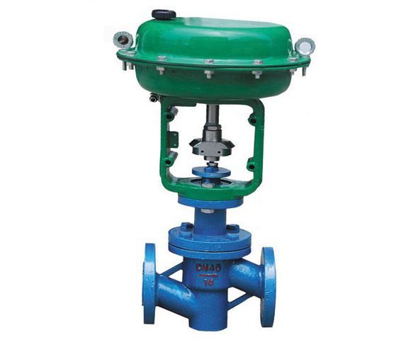
| Product name: | ZMAT type pneumatic diaphragm regulating valve | ||||||
| specification: |  |
||||||
| Category: | Pump valve fittings -- control valve | ||||||
| Price: | factory price | ||||||
| Brand: | |||||||
| Place of Origin: | China | ||||||
| Available Quantity: | batch | ||||||
| delivery cycle: | Spot goods (or inquire by telephone) | ||||||
|
|||||||
|
Nominal diameter mm |
fifteen |
twenty |
twenty-five |
forty |
fifty |
sixty-five |
eighty |
one hundred |
one hundred and fifty |
two hundred | ||
|
Nominal pressure MPa |
0.6 10 | |||||||||||
|
Travel distance mm |
ten |
sixteen |
twenty-five |
forty |
sixty | |||||||
|
flow characteristics |
Approximate quick opening type | |||||||||||
|
Medium temperature ℃ |
-15-200 (normal temperature type), -40 to+250, -40 to+450 (medium temperature type), -100 to+200 (low temperature type) | |||||||||||
|
Flange type |
The sealing surface of the flange shall be in accordance with JB77, with cast iron flanges being smooth and cast steel flanges being concave | |||||||||||
|
Valve body material |
PN (MPa) |
0.6,1.6 |
WCB(ZG230-450) CF3CF8 CF8M | |||||||||
|
4.0,6.4 |
WCB(ZG230-450)、ZG1Cr18Ni9Ti、ZG0Cr18Ni12Mo2Ti CF8 CF8M | |||||||||||
|
Adjustable ratio R |
30:1 | |||||||||||
|
Air source connector |
M16×1.5 | |||||||||||
|
Nominal diameter (mm) |
Equipped with actuator number |
Main technical parameters | ||
|
Effective area of thin film (cm2) |
Travel distance (mm) |
Rated flow coefficient Kv value | ||
|
fifteen |
ZMA(B)-2 |
two hundred and eighty |
ten |
eight |
|
twenty |
twelve | |||
|
twenty-five |
sixteen | |||
|
thirty-two |
ZMA(B)-3 |
four hundred |
sixteen |
twenty-eight |
|
forty |
sixty | |||
|
fifty |
twenty-five |
sixty-eight | ||
|
sixty-five |
ZMA(B)-4 |
six hundred and thirty |
ninety | |
|
eighty |
forty |
one hundred and sixty | ||
|
one hundred |
three hundred | |||
|
project |
technical indicators | |
|
Without locator |
Equipped with locator | |
|
Basic error% |
±10 |
±1.5 |
|
Return difference% |
eight |
one point five |
|
Dead zone% |
six |
zero point six |
|
Allowable leakage amount |
The lining material is polytetrafluoroethylene diaphragm material For: chloroprene rubber, fluororubber |
10-4 times the rated capacity of the valve |
|
The unlined material is, and the diaphragm material is chlorine Nitrile rubber, fluororubber |
5 × 10⁻⁶ × rated capacity of valve | |
|
Can be equipped with accessories |
Electric locator or electric/pneumatic converter, air filter, pressure reducer, solenoid valve, handwheel mechanism, etc | |
|
Deviation of rated flow coefficient Kv% |
±20 | |
Combination of valve body lining and diaphragm material
4. Allow pressure difference |
|
Nominal diameter DN (mm) |
fifteen |
twenty |
twenty-five |
thirty-two |
forty |
fifty |
sixty-five |
eighty |
one hundred | |||
|
Rated flow coefficient Kv |
eight |
twelve |
sixteen |
twenty-eight |
sixty |
sixty-seven |
ninety |
one hundred and sixty |
three hundred | |||
|
Nominal pressure (MPa) |
one | |||||||||||
|
Equipped with actuator model |
ZMA(B)-2 |
ZMA(B)-3 |
ZMA(B)-4 | |||||||||
|
when closed Allow the most high pressure MPa |
letter number press force MPa |
P2=0 |
one hundred and twenty |
zero point nine |
zero point nine |
zero point four zero |
zero point four zero |
zero point three zero |
zero point two |
zero point two |
zero point one |
zero point zero five |
|
one hundred and forty |
one |
one |
zero point eight zero |
zero point eight zero |
zero point six zero |
zero point four |
zero point four |
zero point two |
zero point one zero | |||
|
P1=P2 |
one hundred and twenty |
zero point four five |
zero point four five |
zero point two zero |
zero point two zero |
zero point one five |
zero point one |
zero point one |
zero point zero five |
zero point zero two | ||
|
one hundred and forty |
zero point nine |
zero point nine |
zero point four zero |
zero point four zero |
zero point three zero |
zero point two |
zero point two |
zero point one |
zero point zero five | |||
|
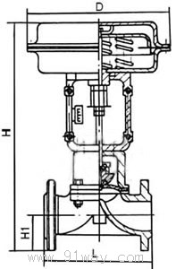
Nominal Diameter DN(mm) |
Exterior installation dimensions | ||||
|
A |
H |
H1 |
L | ||
|
ZMAT type |
ZMBT type | ||||
|
fifteen |
two hundred and eighty |
four hundred and seventy-nine |
five hundred and thirty-two |
forty-seven point five |
one hundred and forty |
|
twenty |
four hundred and seventy-nine |
five hundred and thirty-two |
fifty-two point five |
one hundred and forty-five | |
|
twenty-five |
four hundred and seventy-nine |
five hundred and thirty-two |
fifty-seven point five |
one hundred and fifty-five | |
|
thirty-two |
three hundred and twenty-five |
five hundred and thirty-eight |
six hundred and seventeen |
sixty-seven point five |
one hundred and sixty-five |
|
forty |
five hundred and fifty-three |
six hundred and thirty-two |
seventy-two point five |
one hundred and ninety | |
|
fifty |
five hundred and sixty-two |
six hundred and forty-one |
eighty |
two hundred and ten | |
|
sixty-five |
four hundred and ten |
seven hundred and fifty-four |
eight hundred and fifty-five |
ninety |
two hundred and forty |
|
eighty |
100% |
eight hundred and seventy-six |
ninety-seven point five |
two hundred and seventy | |
|
one hundred |
eight hundred and fifty-seven |
nine hundred and fifty-eight |
one hundred and seven point five |
three hundred and thirty-five | |
Note: The flange is selected according to JB78-59 "Cast Iron Flanges" standard
Home|Quality Commitment|Ordering|Payment method|product delivery|support|Disclaimer|Contact Us
Copyright®2011 www.91way.com Copyright.
Phone:+86-21-66770508 +86-13916500500 Fax:+86-21-66108310
Email:91way@163.com Wechat:40606422
沪ICP备2021005791号 ![]() 沪公网安备31010702003255号
沪公网安备31010702003255号