
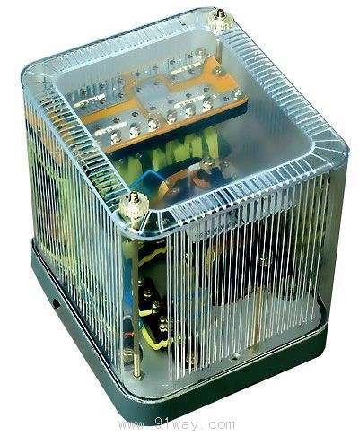
| Product nameŁş | BCH-1 type differential relay | ||||||
| specificationŁş |  |
||||||
| CategoryŁş | low-voltage electrical apparatus -- Differential relay | ||||||
| PriceŁş | factory price | ||||||
| BrandŁş | |||||||
| Place of OriginŁş | China | ||||||
| Available QuantityŁş | batch | ||||||
| delivery cycleŁş | Spot goods (or inquire by telephone) | ||||||
|
|||||||
1 Purpose
The BCH-1 differential relay has a braking winding that can provide single-phase differential protection for two winding and three winding power transformers.
Overview of Structure 2
The BCH-1 differential relay consists of a DL-11 electromagnetic current relay (actuator) and an intermediate fast saturation converter (hereinafter referred to as the converter).
Relays have braking windings, which constitute some of the main technical properties of differential relays, such as braking characteristics, avoidance of excitation inrush current characteristics, and performance of autotransformers to eliminate unbalanced current effects.
The magnetic conductor of the inverter is a three column iron core, composed of several sets of "mountain" shaped magnetic plates stacked together. The working winding and balance winding I and II are placed on the middle column of the magnetic conductor, while the braking winding and secondary winding are divided into two parts and placed on the two side columns of the magnetic conductor. The connection method should ensure that there is no mutual induction between the braking winding, secondary winding, and balance winding I and II. The induced potential in the secondary winding is generated by the magnetization of the working winding. In order to change the degree of saturation of the inverter magnetic conductor, the number of turns of the braking winding can be changed.
The inverter can prevent both excitation inrush current and relay misoperation during power transformer fault crossing. Inverter and actuator
The components are placed in a casing, and the relay can be wired in front of and behind the board during installation. The schematic diagram of the inverter wiring is shown in Figure 1, and the external wiring of the relay for protecting the three winding power transformer is shown in Figure 2.
The setting plug on the corresponding hole of the inverter connection board can be used to adjust the operating current, balance coefficient, and braking coefficient. The number on the hole represents the number of turns of the inserted winding when it is set in that hole.
Figure 1
Figure 2
3 Technical data
3.1 Rated current 5A, rated frequency 50Hz.
3.2 When there is no braking, the starting action of the relay is AWo=60 ˇŔ 4.
When used to protect a three winding power transformer, its operating current can be set within the range of 3A to 12A (AWo=60),
For the minimum setting value of the action, its maximum balance coefficient is close to 2.
When used to protect a two winding power transformer, its operating current can be set within the range of 1.55A to 12A.
The braking coefficient Kz determined by the ratio of action current to braking current can vary widely, as shown in Figure 3
The characteristic AWp=f (AWz) is its limit range, which is related to the phase angle between the operating current and the braking current, but regardless of the angle
It should not exceed the range of the curve.
3.5 Reliability coefficient (the sine current of the relay when one action current is equal to 5IDZ and the sine current of the relay when one action current is equal to IDZ)
The ratio of operating currents shall not be less than 1.35.
The action time of the differential relay with 3 times the action current shall not exceed 0.035s.
3.7 The relay has a dynamic contact, and in a DC circuit with inductive loads, the breaking capacity of the contact is 50W when the time constant is not greater than 5 ˇÁ 10-3s, the voltage is not greater than 220V, and the current is not greater than 2A.
3.8 Under normal operating conditions, when the current is 5AK, the single-phase power consumption of the relay shall not exceed 8.5VA when the brake winding balance winding of the inverter is fully turned on.
The working, balancing, and braking windings of the 3.9 inverter can pass a current of 10A for a long time.
3.10 Dielectric strength: The circuit of the relay should be able to withstand an AC voltage of 2kV, 50Hz for 1 minute without breakdown or flashover between the exposed non charged metal parts.
The weight of the 3.12 relay shall not exceed 4kg.
The winding data of relay 3.13 is shown in Table 1.
|
Winding |
Winding data |
Remarks |
|
work |
Wp=20 turns with a diameter of 1.81 |
|
|
Balance I, II |
Wy=19 turns (per piece) with a diameter of 1.81 | |
|
braking |
2 ˇÁ Wz=2 ˇÁ 14 turns with a diameter of 1.8l | |
|
second |
2 ˇÁ W2=2 ˇÁ 24 turns, with a diameter of 1.45 | |
|
Execution element DL-11 type relay |
2 ˇÁ W=2 ˇÁ 500 turns, with a diameter of 0.38 |
Two coils in parallel |
HomeŁüQuality CommitmentŁüOrderingŁüPayment methodŁüproduct deliveryŁüsupportŁüDisclaimerŁüContact Us
Copyright®2011 www.91way.com Copyright.
PhoneŁş+86-21-66770508 +86-13916500500 FaxŁş+86-21-66108310
Email:91way@163.com Wechat:40606422
»¦ICP±¸2021005791şĹ ![]() »¦ą«Íř°˛±¸31010702003255şĹ
»¦ą«Íř°˛±¸31010702003255şĹ