
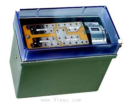
| Product nameŁş | DCD-5A type differential relay | ||||||
| specificationŁş |  |
||||||
| CategoryŁş | low-voltage electrical apparatus -- Differential relay | ||||||
| PriceŁş | factory price | ||||||
| BrandŁş | |||||||
| Place of OriginŁş | China | ||||||
| Available QuantityŁş | batch | ||||||
| delivery cycleŁş | Spot goods (or inquire by telephone) | ||||||
|
|||||||
1 Overview
DCD-5A differential relay (hereinafter referred to as relay) is used in single-phase protection wire bars of two winding or three winding power transformers as the main protection.
1.2 Working conditions of relays
a. The ambient temperature is -25-+40 ˇć;
b. Atmospheric pressure: 80-106kPa (altitude not exceeding 2000m);
c. The relative temperature of the air is 45% to 75%;
d. The reference value for the working position is vertical, with a tolerance of 2 ˇă deviation in any direction;
e. There should be facilities to protect against wind, sand, rain, and snow, as well as an environment free from corrosive and explosive gases;
f. No strong vibration or impact
g. There should be no significant external magnetic field influence in any direction around the usage location.
Basic structure and working principle of DCD-5A differential relay:
2.1 Basic Structure
The relay consists of a highly sensitive and reliable electromagnetic actuator with a pair of dynamic contact points and an intermediate speed saturation converter.
The actuator is an electromagnetic relay, which is used as
Export components.
Figure 1 Schematic diagram of the distribution of windings on magnetic conductors
The magnetic conductor of the inverter is composed of "E" shaped magnetic plates stacked together. The working winding (differential winding), balance winding I, and balance winding II are placed on the middle column of the magnetic conductor. The secondary and braking windings are divided into two halves and wound on the two side columns respectively. The distribution of windings on the magnetic conductor is shown in Figure 1. Internal wiring of relays and principle wiring for protecting three winding power transformers
As shown in Figure 2. Due to its balanced winding and tap every turn for adjustment, it is used to eliminate the effect of unbalanced current caused by inconsistent current transformer ratios and other reasons. Having two balanced windings enables relays to be used to protect three winding power transformers.
The operating current, balancing effect, and braking characteristics can be tuned over a wide range of turns through the working winding, balancing winding, and braking winding.
2.2 Basic Principles
When a short circuit passes through the current in the braking winding, the magnetic conductor of the inverter is saturated, thus deteriorating the current induction conditions from the differential winding and balance winding to the secondary winding while ensuring the same braking characteristics. The two halves of the secondary winding and braking winding are connected in such a way that the potential in the two windings is caused by the magnetic flux of the working winding. In order to change the saturation degree of the magnetic conductor of the inverter, the number of turns of the braking winding is made adjustable.
The use of inverters can simultaneously prevent excitation inrush current and relay misoperation during no-load closing of power transformers.
The foot actuator connected to the secondary winding of the inverter. And specify its operating voltage and operating current. The operating voltage reflects the working magnetic flux density of the inverter, and the operating current determines the power distribution ratio of the inverter, while meeting the requirements of universality in production. The characteristic of this type of actuator is that its coil is sufficiently inductive, and there are significant high-order harmonics in the secondary induced potential when the inverter is saturated. Therefore, this type of actuator is a good high-order harmonic filter, which basically reflects the fundamental wave of the inverter's working magnetic flux density.
The schematic wiring diagram of DCD-5A differential relay is shown in Figure 2.
Figure 2 Schematic wiring diagram of relay internal and maintaining three winding power transformer
Main technical performance and parameters of DCD-5A differential relay
3.1 Rated value
Rated current 5A, rated cycle rate 50Hz.
When there is no DC component, the relay starts to operate with an ampere turn Awo of 60 ˇŔ 4.
When used to protect a three winding transformer, the operating current of the relay can be set within the range of 3-12A (AWo=50), and for the minimum setting value of the operating current, its maximum balance coefficient is close to 2.
When used to protect a two winding transformer, the operating current can be adjusted within a finer range of 1.55-12A (Awo=60).
3.4 Braking coefficient
The operating current of the relay in the working winding can change the current in the braking winding (the ratio when AWT=280).
a. For maximum setting action current above 0.18;
b. For 3A, the setting action current is below 0.63;
Figure 3 shows the relationship curve of Awp=f (AWr) when there are different phase shift angles between the braking current and the operating current. From Figure 3, it can be seen that the relationship between the braking coefficient and the phase shift angle between the operating current and the braking current cannot exceed these two characteristic curves.
3.5 Reliability coefficient
The reliability coefficient of the relay should not be less than 1.35.
When the differential relay operates, its operating current is ICP, and the sine operating current of the actuator is iCP. Then, rotate the pointer and tighten the balance spring to make the operating current of the relay 5ICP. Measure the corresponding sine operating current ICP5 of the actuator, and calculate the reliability coefficient according to the following formula.
Kh=Icp1/Icp5
Figure 3 Relationship curve of AWp=f (AWr) between braking current and operating current with different phase shift angles
In the same situation, when the operating current of the differential relay is 2ICP, the above ratio is not less than 1.2.
When the operating current is 3 times that of 3.6, the operating time of the differential relay shall not exceed 0.035s.
3.7 Efficiency consumption
At rated current, the single-phase power consumption of the relay should not exceed the following specifications.
a) Under normal circumstances, when all the turns of the braking and balancing windings of the inverter are connected, it should not exceed 8.5VA.
b) When there is a fault in the area, the braking, balancing, and number of turns of the working winding of the inverter should not exceed 20VA.
Under normal circumstances, the working winding, braking winding, and balancing winding of the relay can pass a current of 10A for a long time.
3.9 Contact Performance
The relay contacts should be able to disconnect a DC circuit with a voltage not exceeding 250V and a current not exceeding 2A, and a capacity of 50W inductive load (time constant of 5 ˇŔ 0.75ms). Under this specified load condition, the relay should operate reliably 1000 times.
3.10 Mechanical lifespan
The mechanical lifespan of the relay is 104 times.
3.11 The conductive circuits of the relay connected together to the ground (or the exposed non-conductive metal parts of the insulation shell) and the conductive circuits that are not electrically connected should withstand an AC test voltage of 2KV (effective value) 50Hz for 1 minute without insulation breakdown or flashover.
3.12 The relay can withstand an impulse voltage of 5kV without insulation damage thereafter.
The weight of the 3.13 relay is approximately 5kg.
The winding data of DCD-5A differential relay is shown in Table 1.
|
winding |
Winding data |
Core cross-sectional area |
remark |
|
work |
Wp=20 turns 1.81 double yarn wrapped copper wire |
S=1.25cm2 (Side pillar) |
Each winding Tap as shown in Figure 2 |
|
Balance I and II |
WY1=WY2=19 turns 1.81- Double yarn wrapped copper wire | ||
|
second |
2 ˇÁ W2=48 turns 1.45 double yarn wrapped copper wire | ||
|
braking |
2 ˇÁ Wz=2 ˇÁ 14 turns 1.81- double yarn wrapped copper wire | ||
|
Execution element |
2 ˇÁ W 2 ˇÁ 380 turns QQ-0.5 enameled copper wire |
S=2.64cm2 |
Two coils in parallel |
4. Use and Maintenance
4.1 Setting of working winding, balancing winding and braking winding
Open the shell cover to adjust the working winding, balance winding, and brake winding. The working winding, balancing winding, and braking winding all have taps that can meet the requirements of various setting values. The number below the relay setting board represents the corresponding winding turns. The balanced winding and the working winding are each divided into two sections for tuning. This design can use fewer taps to obtain more combinations of turns, thus making the tuning range wide and precise. Each tuning board has two tuning screws, each of which can be tuned within its own range. The sum of the numbers marked at the tuning positions of the two screws is the number of turns for the winding. (It should be noted that when two set screws on the same setting board are not set within their respective ranges or are not connected, the winding will be disconnected.)
When a circuit breaker is used to protect a three winding power transformer, two balanced windings should be applied and connected to the two arms of the circulating current circuit, so as to balance the effect of unbalanced currents in the three circulating current circuits. When used to protect a two winding power transformer, only one balanced winding is required. In the case of a large unbalanced current, the balanced winding is connected to the circulating current circuit. When the unbalanced current is small or used to protect the AC generator, the balanced winding can be connected to the working circuit to expand the range of setting values. The role of the balanced winding can be represented by the balance coefficient determined by the ratio of the secondary currents of two current transformers. The actual balance coefficient should be calculated based on the number of turns connected to the winding. According to the circuit in Figure 4, I1 and I2 respectively represent the secondary currents of two current transformers, and I1 is greater than I2. The balanced winding is usually connected to the circulating arm with the smaller current. When the synthetic magnetization force of the working circuit is zero, the effect of unbalanced current is completely eliminated, thus obtaining the following equation:
(I1-I2) WP I2 WY=0 (1) or I1WP=I2 (WP+WY) (2)
The equilibrium coefficient KY is: Ky=I1/I2=(Wp+Wy)/Wp
The initial action of the relay's ampere turns can be adjusted within a small range using potentiometer W. When adjusting, first loosen the fastening nut, and then use a "-" shaped screwdriver to adjust the potentiometer handle.
During the operation of the relay, attention should be paid not to change the position of the pointer on the nameplate.
6 Ordering Instructions
Please specify when placing an order
6.1 Name and model of relay.
6.2 Rating of Relays.
6.3 Relay appearance structure code.
6.4 Order quantity.
Figure 4: Schematic wiring diagram of relays used to protect two winding power transformers
Figure 5 Appearance and installation dimensions of DCD-5A differential relay
HomeŁüQuality CommitmentŁüOrderingŁüPayment methodŁüproduct deliveryŁüsupportŁüDisclaimerŁüContact Us
Copyright®2011 www.91way.com Copyright.
PhoneŁş+86-21-66770508 +86-13916500500 FaxŁş+86-21-66108310
Email:91way@163.com Wechat:40606422
»¦ICP±¸2021005791şĹ ![]() »¦ą«Íř°˛±¸31010702003255şĹ
»¦ą«Íř°˛±¸31010702003255şĹ