1 Purpose
DCD-2A differential relay (hereinafter referred to as relay) is used as the main protection in single-phase differential protection lines of two winding or three winding power transformers and AC generators.
Relays can prevent transient currents that occur in non fault states. For example, when a power transformer is closed without load or after a transient short circuit is cut off, there is a large excitation inrush current when the voltage is restored, and its instantaneous value often reaches 5-10 times the rated current; At this time, the differential protection should not malfunction, but it can quickly cut off the fault when a short circuit occurs within the area.
2 Structure and working principle
2.1 Structure
The relay consists of a highly sensitive and reliable electromagnetic actuator with a pair of dynamic contact points and an intermediate speed saturation converter. The actuator is an electromagnetic relay, which is used as an outlet component in the relay.
Intermediate speed saturated converters have short-circuit windings and balanced windings, which constitute some of the main technical performance of differential relays, such as the performance of DC bias characteristics to eliminate unbalanced current effects in autotransformers.
The magnetic conductor of the inverter is composed of stacked "E" magnetic plates, with balanced windings I and II and short-circuit windings. In addition, the short-circuit winding on the middle column is connected to the short-circuit winding on the right side column through a ceramic potentiometer, and the secondary winding is placed on the other side column of the magnetic conductor. The distribution of windings in the magnetic conductor is shown in Figure 1. The internal wiring of the relay and the principle wiring diagram for protecting a three winding power transformer are shown in Figure 2. Due to its balanced winding and tap every turn, it is easy to adjust and eliminate the effect of unbalanced current caused by inconsistent current transformer ratios. Having two balanced windings enables relays to be used to protect three winding power transformers.
The action current and balancing effect can be adjusted within a wide range by adjusting the number of turns of the working winding and balancing winding. The DC bias characteristic can be adjusted by changing the resistance of the ceramic potentiometer of the relay.
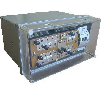
The structural form, appearance, installation dimensions, and terminal wiring of the relay are shown in Figure 6.
2.2 Principle
The basic principle of a relay is to use the non periodic component of the transient current during non fault conditions to magnetize the magnetic conductor of the inverter, increase its saturation level, and thus avoid the effect of excitation inrush current and unbalanced current during transient faults. The corresponding characteristic curve is the DC bias characteristic curve cluster ¦Ĺ 2f (K). Differential circuit connected to the working winding for protection; The balanced winding can be connected to the loop or working circuit according to actual needs.
The inverter with short-circuit winding is characterized by the specialized use of non periodic current to magnetize the magnetic conductor. Figure 3 shows the electromagnetic process inside the magnetic conductor. When the power transformer is closed under no-load, the excitation inrush current with a large instantaneous value flows through the working winding, and the waveform of the inrush current has a magnetic flux biased towards the time axis. They produce two different reactions in the short circuit group. Under the action of DC magnetic flux, the magnetic conductor quickly saturates, greatly reducing the magnetic permeability. This greatly deteriorates the electromagnetic induction conditions between the working winding and the secondary winding, thus significantly increasing the operating current of the relay, which is called DC bias phenomenon.
When there is a transient short circuit and the short-circuit current contains non periodic component currents, the same effect is also produced, which can prevent misoperation when the transient short circuit is cut off and the voltage is restored. The DC bias characteristic of the relay is represented by the curve family of Figure 4, denoted as f (K).
Among them, ¦Ĺ=Icp/Icpo, the multiple of the operating current, is the ratio of the AC operating current with a DC component to the AC current with a DC component equal to zero.
K=I=/IcpŁ¬ The offset coefficient, which is the ratio of the DC component to the corresponding AC operating current, represents the degree of deviation of the current waveform from the time axis.
The above ¦Ĺ=f (K) is the static characteristic of the relay, which was obtained by testing the simultaneous application of AC and DC currents in the working winding. DC current does not change with time, while the value of non periodic component current gradually decays with the increase of time.
In order to achieve better speed saturation characteristics, a higher working magnetic flux density Bcp was selected in the design of the inverter. However, to ensure the necessary capacity for reliable relay operation, it is stipulated that the reliability coefficient KH should not be less than 1.35 when the operating current of the relay is 5 times the starting value.
The working magnetic flux density of the inverter is determined by the weight of the magnetic material and the initial operating voltage and current. The operating voltage reflects the operating magnetic flux density of the inverter; The action power determines the power distribution ratio of the inverter and meets the requirements of universality in production. The characteristic of this type of actuator is that its coil is inductive. In the case of inverter saturation, the secondary induced potential contains significant high-order harmonic filters. Therefore, this type of actuator is a good high-order harmonic filter, which basically reflects the fundamental wave of the inverter's working magnetic flux density.
The principle wiring of the relay is shown in Figure 2.
Technical performance and parameters of DCD-2 differential relay:
3.1 Rated value
Rated current 5A, rated power 50Hz.
When there is no DC component, the relay starts to operate with an ampere turn Awo of 60 ˇŔ 4.
When used to protect two winding power transformers or AC generators, the operating current can be set within the range of 3-12A (Awo=60). For the minimum setting value of the operating current, the maximum balance coefficient is close to 2.
When used to protect two winding power transformers or AC generators, the operating current can be set within the range of 1.55-12A.
The DC bias characteristic of the 3.5 relay is ¦Ĺ=f (K), which can be continuously adjusted by changing the resistance value of the ceramic disc variable resistor.
When the offset coefficient K is 0.6, the error of the relative operating current coefficient of the DC bias magnetic characteristics at each setting position does not exceed -8% to+20%. The reliability coefficient of the relay should not be less than 1.35.
When the differential relay operates, its operating current is lCPO, and the corresponding sine operating current of the actuator is icpl. Then, rotate the pointer and tighten the balance spring to make the operating current of the relay 5Icp and measure the corresponding sine operating current icp5 of the actuator. Calculate the reliability factor according to the following formula: Kn=Icp5/icp1.
In the same situation, when the operating current of the differential relay is 2ICP, the above value is not less than 1.2.
When the operating current is 3.7 times, the operating time of the differential relay shall not exceed 0.035 seconds.
When all the turns of a balanced winding and a working winding of the inverter are connected, there is a fault in the protection zone and the current is equal to 5A. The single-phase power consumption of the relay does not exceed 16VA.
Under normal circumstances, the transformation ratio error of the current transformer is fully compensated (the magnetization force of the inverter working circuit is balanced, and the magnetic flux in the magnetic field is moldy). The next work involves winding molybdenum and balancing thin wires, which can withstand a current of 10A for a long time.
It is a test conducted by applying direct current when all turns of the balanced winding and working winding are connected.
The DC resistance of the working winding or each balanced winding should not exceed 0.05 ¦¸.
3.11 Contact Performance
The relay contacts should be able to disconnect inductive loads with a voltage not exceeding 250V and a DC not exceeding 2A, and a capacity of 50W (time constant)
For a DC circuit of 5 ˇŔ 0.75ms, the relay should reliably operate 1000 times under this specified load condition.
3.12 Mechanical lifespan
The mechanical lifespan of the relay is 104 times.
3.13 The conductive circuits of the relay connected together to the ground (or the exposed non-conductive metal parts of the insulation shell) and the conductive circuits that are not electrically connected should be able to withstand an AC test voltage of 2kV (effective value) 50Hz for 1 minute without insulation breakdown or flashover.
3.14 The relay can withstand an impulse voltage of 5kV without insulation damage thereafter.
The weight of the 3.15 relay is approximately 6kg.
The winding data of the 3.16 relay is shown in Table 1.
|
Winding |
Winding data |
Core cross-sectional area |
remark |
|
work |
Wp=20 turns 1.56-SBEC double yarn wrapped copper wire |
S=1.25cm2
(Side pillar) |
Each winding tap
See Figure 2 |
|
Balance I and II |
WYl=WY2=19 turns 156-SBEC double yarn wrapped copper wire |
|
second |
W2=48 turns 1.0-SBEC double yarn wrapped copper wire |
|
Execution element |
2W=2 ˇÁ 380 turns QQ-0.51 enameled copper wire |
S=2.64cm2 |
Two coils in parallel |
4 Working conditions
4.1 The ambient temperature ranges from -25 ˇć to 40 ˇć.
4.2 Atmospheric pressure: 80-106kPa (altitude not exceeding 2000 meters).
4.3 The relative temperature of the air is 45% to 75%.
The reference value for the working position is vertical, with a tolerance of 2 ˇă deviation in any direction.
4.5 There should be facilities to protect against sandstorms, rain, and snow, as well as an environment free from corrosive and explosive gases.
4.6 No strong vibration or impact.
4.7 There should be no severe external magnetic field influence in any direction around the usage location.
5. Use and Maintenance
5.1 Setting of working winding and balancing winding.
Open the shell cover to adjust the working winding and balance winding. The working winding and balance windings I and II have taps that can meet the requirements of various setting values. The number below the relay setting board represents the corresponding winding turns. Each winding is divided into two sections, and this design allows for fewer taps to obtain more combinations of turns, thereby enabling a wide range of tuning without losing its precision. There are two setting screws on each relay setting board, and each setting screw can be set within its own range. The sum of the numbers marked at the set positions of the two screws is the set number of turns of the winding.
It should be noted that when two setting screws on the same setting board are set within their respective ranges or not connected, the winding is disconnected.
5.2 Adjustment of magnetic characteristic curve
When setting the magnetic assistance characteristic curve, the relay core needs to be removed, and then the three large screws that lock the ceramic disc variable resistor on the magnetic assistance characteristic signboard need to be loosened (do not unscrew, just loosen them), so that the knob can rotate freely. Rotate the knob to adjust the magnetic characteristic curve.
5.2.1 Curve tuning according to regulations
The relay has four curves: A, B, C, and D. These four curves have been carefully debugged according to technical requirements before the relay leaves the factory, so simply align the arrow on the knob with the desired setting point.
5.2.2 Special Requirements Setting
If the curve needs to be adjusted within the range between curves A and D, but not on curves A, B, C, and D, the following method can be used for adjustment:
1) Determine the ¦Ĺ value of the curve at K=0.6 based on the required ¦Ĺ 2-f (K) curve.
2) Determine the required DC current value to be added during the experiment.
Apply current between terminals ˘Ů and ˘á, set the working winding to 20 turns and the balance winding to 19 turns, and then measure the initial sinusoidal current value lCPO. Calculate the DC current I=KICPO=0.6Icp based on K=0.6 and
3) Determine the position of the disk variable resistor
Calculate the AC operating current ICP=¦Ĺ ICPO when there is a DC component, as specified in Article 1; ICPO is measured according to Article 2). Set the working winding and balance winding to 20 turns and 19 turns respectively, and add the previously calculated DC current value I and AC operating current ICP between terminals ˘Ů and ˘á. Adjust the variable resistor to make the relay's operating current ICP.
4) If precise tuning is required, the indication of the variable resistor knob can be temporarily kept at the previously set position, and then the subsequent tuning steps from point 2) can be repeated until the tuning position of the variable resistor no longer changes. Due to the change in resistance of the variable resistor, the initial action ampere turns can vary within a small range.
After setting the magnetic characteristic curve, the three locking screws should be evenly tightened.
When a relay is used to protect a three winding power transformer, two balanced windings should be applied and connected to the two arms of the circulating current circuit, so as to balance the effects of unbalanced currents in the three circulating current circuits. When used to protect a two winding power transformer, only one balanced winding needs to be applied. In the case of a large unbalanced current, the balanced winding is connected to the circulating current circuit. When the unbalanced current is small or used to protect the AC generator, the balanced winding can be connected to the working circuit to expand the range of setting values. The role of the balanced winding can be represented by the balance coefficient determined by the ratio of the secondary currents of two current transformers. The actual balance coefficient should be calculated based on the number of turns connected to the winding. According to the circuit in Figure 6, I1 and I2 respectively represent the secondary currents of the two current transformers, and the balanced winding is usually installed on the current arm. When the synthetic magnetization force of the working circuit is zero, the effect of unbalanced current is completely eliminated, thus obtaining the following equation:
(I1-I2) WP-I2Wr=0 or I1WP=I2 (WP+Wr) (1)
The equilibrium coefficient KY is Ky=I1/I2=(Wp+Wr)/Wp (2)
The initial action of the relay's ampere turns can be adjusted within a small range using potentiometer W. When adjusting, first loosen the fastening nut, and then use a straight screwdriver to adjust the potentiometer handle.
During the operation of the relay, care should be taken not to change the position of the pointer on the nameplate.
6 Ordering Instructions
6.1 Name and model of relay.
6.2 Rated value of relay.
6.3 Number of relays.
Figure 1 Distribution of winding in magnetic conductor Wp Working winding Wr Balanced winding I, II W2 Secondary winding Wko Short circuit winding
Figure 2 Schematic wiring diagram of internal wiring of relay and protection of three winding power transformer
Figure 3 Schematic diagram of magnetization process inside the magnetic conductor
Wp working winding Wy1 Wy2- balanced winding I, II W'ky W ''ky - short-circuit winding W2- secondary winding
P-magnetic flux generated by working winding oky magnetic flux generated by short-circuit winding
O=DC magnetic flux generated by non periodic component current flowing through the working winding
Figure 4: Cluster of magnetic assist characteristic curves and adjustment range of DCD-2 differential relay (R: 0~12W)
Figure 5 LH current transformer BY transformer WP differential winding WY balanced winding

Figure 6 Appearance and installation dimensions of DCD-2 differential relay