
| Product nameŁş | BCH-2 type differential relay | ||||||
| specificationŁş |  |
||||||
| CategoryŁş | low-voltage electrical apparatus -- Differential relay | ||||||
| PriceŁş | factory price | ||||||
| BrandŁş | |||||||
| Place of OriginŁş | China | ||||||
| Available QuantityŁş | batch | ||||||
| delivery cycleŁş | Spot goods (or inquire by telephone) | ||||||
|
|||||||
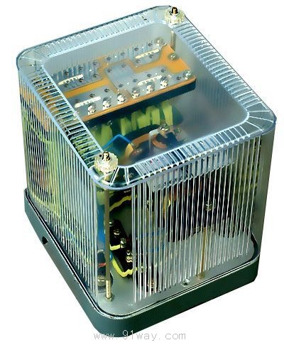
BCH-2 type differential relay
1 Purpose
BCH-2 differential relay is used for single-phase differential protection of two winding and three winding power transformers, as well as AC generators.
Relays can prevent protection from non selectively acting due to unstable transient currents caused by non fault conditions (such as short-circuit currents or transformer no-load closing).
Overview of Structure 2
This relay consists of an electromagnetic current relay DL-11 and an intermediate speed saturation converter.
Relays have short-circuit windings, which constitute some of the main technical properties of differential relays, such as the performance of DC bias characteristics to eliminate unbalanced current effects in autotransformers.
All windings of the speed saturation converter are made with taps, so that the parameters of the relay can be adjusted step by step.
When using BCH-2 type relays to protect power transformers, the number of turns of the balanced winding is selected based on the condition that when a crossing short circuit occurs, the number of turns of all windings should be equal.
When a relay is used to protect a two winding transformer, the operating current can be adjusted within a more detailed range, as two balanced windings can be utilized at this time.
The inverter and the actuator are placed in the same housing. In order to facilitate separate verification, adjustment, and testing of the inverter characteristics, the coil of the actuator is connected to the secondary winding, balance winding, and working winding of the inverter through a connecting plate. Therefore, the corresponding circuit can be connected or disconnected during adjustment and testing.
Do not change the position of the pointer on the relay nameplate (do not leave the nameplate scale) or move the spring fixing screw without moving the pointer. This will deteriorate the ability to avoid the influence of non periodic components of magnetizing current or unbalanced current, or reduce the reliability coefficient of the relay when a short circuit occurs within the protection zone. The schematic diagram 1 of the inverter wiring and the external wiring diagram of the relay for protecting the three winding power transformer are shown in Figure 2.
Figure 1
Figure 2
Figure 3 DC magnetic assist characteristic curve
3 Technical data
3.1 Rated current 5A, rated frequency 50Hz.
The starting action of the relay is 60 ˇŔ 4 ampere turns.
3.3 The DC magnetization characteristic curve of the relay (as shown in Figure 3) ¦Ĺ=f (K) should be able to be adjusted in sections;
The ratio of the K-DC component to the corresponding AC operating value.
When ¦Ĺ - has a DC component, the ratio of the AC operating current of the relay to the AC operating current without a DC component.
Figure 3 shows the ¦Ĺ=f (K) curve cluster when the short winding is connected to different turns. When K=0.6, the corresponding ¦Ĺ value for each short-circuit coil tap should comply with the following regulations:
Short circuit winding tap position: ¦Ĺ: A-A, 1.6 ˇŔ 0.13; B-BŁ¬3ˇŔ0.24Ł» C-CŁ¬5ˇŔ0.38Ł» D-DŁ¬7ˇŔ0.56Ł»
3.4 The reliability coefficient should not be less than 1.35, and the reliability coefficient should be determined according to the following method: assuming the operating current of the relay is Id, the corresponding operating current of the DL-11 type relay is i1; Then rotate the pointer and tighten the balance spring to make the operating current of the differential relay 5Id. Measure the corresponding operating current i5 of the actuator, and calculate the reliability coefficient according to the following:
KK=
When the operating current is 3.5 times, the operating time of the differential relay shall not exceed 0.035s;
When the voltage does not exceed 220V and the current does not exceed 2A, the breaking capacity of the relay contacts in a DC inductive load (time constant of 5 ˇÁ 10-3s) circuit is 50W.
At rated current, when the balance winding (1 or II) and the number of turns of the working winding of the relay are all connected, the single-phase power consumption of the relay should not exceed 16VA
When the temperature of the surrounding medium is+40 ˇć, the working winding and a balancing winding of the relay should be able to pass 10A current for a long time, and the temperature rise should not exceed 60K.
3.9 Dielectric strength: Each circuit of the relay should withstand an AC voltage of 50Hz and 2kV for 1 minute without breakdown or flashover between the exposed non charged metal parts.
3.10 When all the turns of each winding are connected and the short-circuit winding is connected at position A-A, their impedance values are shown in Table 1.
|
Winding |
At the following current values (A) and impedance Z (¦¸) |
DC resistance (¦¸) | ||
|
three |
five |
ten | ||
|
Work |
zero point three two |
zero point two eight |
zero point one nine |
zero point zero four |
|
Balance ||| |
zero point three |
zero point two seven |
zero point one eight |
0.042-0.044 |
|
Winding |
Winding data |
remark |
|
Work |
Wp=20 turns with a diameter of 1.56 |
|
|
Balance I, II |
Wy=19 turns (per piece) ¦µ 1.56 | |
|
Short circuit (center pillar) |
W'Kz=28 turns with a diameter of 1.45 | |
|
Short circuit (side pillar) |
W "Kz=56 turns with a diameter of 1.45 | |
|
second |
W2=48 turns with a diameter of 1.0 | |
|
Execution element DL-11 type relay |
2W, 2 x 500 turns, with a diameter of 0.38 |
Two coils in parallel |
HomeŁüQuality CommitmentŁüOrderingŁüPayment methodŁüproduct deliveryŁüsupportŁüDisclaimerŁüContact Us
Copyright®2011 www.91way.com Copyright.
PhoneŁş+86-21-66770508 +86-13916500500 FaxŁş+86-21-66108310
Email:91way@163.com Wechat:40606422
»¦ICP±¸2021005791şĹ ![]() »¦ą«Íř°˛±¸31010702003255şĹ
»¦ą«Íř°˛±¸31010702003255şĹ