The KTJ17 series AC cam controller (hereinafter referred to as the controller) is suitable for power lines with AC 50HZ and voltage below 380 volts. It is used to change the three-phase asynchronous motor stator circuit connection or rotor circuit resistance value to directly control the starting, speed regulation, braking or commutation of the motor.
Classification and Model Meaning
1. Classification: Classified by operation method:
Horizontal rotation operation;
Vertical reciprocating operation.
2. KTJ17 series AC cam controller model meaning:
Normal working conditions
Surrounding air temperature
The maximum air temperature around does not exceed+40 ℃.
The lower limit of ambient air temperature shall not be lower than -5 ℃.
The average value within 24 hours shall not exceed+35 ℃. Note: When used for -10 ℃ or -25 ℃, users should indicate it when placing an order.
Altitude: The altitude of the installation site shall not exceed 2000 meters.
Atmospheric conditions
The relative humidity of the atmosphere does not exceed 50% when the highest temperature around is+40 ℃, and can have higher relative humidity at lower temperatures. At the same time, when the monthly average lowest temperature is 25 ℃, the average maximum relative humidity of the wettest month is 90%, taking into account the condensation that occurs on the surface of the product due to temperature changes.
Pollution level: The pollution level of the controller is level 3.
Installation category: The installation category of the controller is Class III.
Note: Any use beyond the above conditions should be resolved through a special ordering agreement between the supply and demand parties.
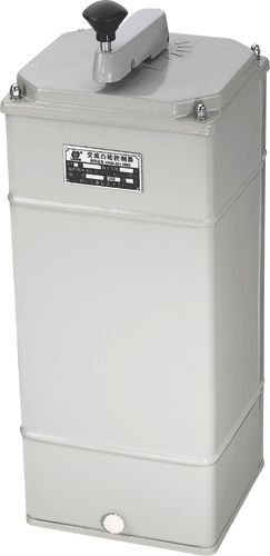
Overview of the Structure of KTJ17 Series AC Cam Controller
The controller has a protection level of IP30 and is installed vertically.
The controller is divided into four parts: the control mechanism part, the cam and contact system part, and the housing part. The control handle is equipped with a zero position self-locking device to prevent the control mechanism from moving due to crane vibration and accidental collision. When operating, simply press down the handle and open the zero position self-locking device to operate.
The mechanical transmission part is installed on the upper part of the box, and the vertical operating handle rotates the camshaft through a bevel gear. The horizontal operating handle directly rotates the camshaft to open and close the contact group according to the prescribed program. The camshafts of the controller are all installed vertically. Rolling bearings are used at each pivot point of the transmission loop to reduce friction.
The positioning ratchet is stamped from 3mm thick steel plate and undergoes appropriate heat treatment to achieve good wear resistance. The controller has six gear positions. Within the range of six gears on each side. The number of gears can be freely selected. The positioning ratchet spring force can be adjusted, so that the ratchet spring force can be adjusted according to the specific situation, under the premise of clear gear classification, to make the handle operating force within the allowable range.
The contact group structure is a rotating double break point. The installation dimensions of the 32A and 63A contact groups are the same, so they are commonly used for installing support rods. The machine base is made of die cast aluminum parts, and the upper panel is formed by stretching steel plates. The machine base and panel are connected by four pillars, which have the characteristics of light weight and good rigidity. The front and rear covers can be easily removed for installation, wiring, and maintenance purposes.
Technical data
1. Handle operating force: not exceeding 40N.
2. Maximum control gear: left, right, and 6th gear.
3. The maximum number of control circuits is 21 for KTJ7.
4. The electrical performance of the auxiliary contact group of the controller meets the technical specifications of the main controller.
5. The 32A controller can directly control wound motors of 15 kW and below.
6. The 63A controller can directly control wound motors of 30 kW and below.
7. The mechanical lifespan shall not be less than 1.5 million cycles.
8. The on-off capability of the main circuit of the cam controller meets the AC2 usage category; The on-off capability of the auxiliary circuit should comply with the AC-15 usage category, and its specific values are shown in Table 1.
|
Usage category |
Rated working current (A) |
Connection conditions |
Breaking conditions |
Number of on-off cycles |
Interval time (S) |
Power on time (S) |
|
L(A) |
U(V) |
COSФ |
L(A) |
U(V) |
COSФ |
|
AC2 |
thirty-two
sixty-three |
eighty
two hundred and fifty-two |
four hundred and eighteen |
0.65 |
one hundred and twenty-eight
two hundred and fifty-two |
four hundred and eighteen |
0.65 |
twenty-five |
5~10 |
Connection ≥ 0.05
Breaking ≤ 0.5 |
|
AC-11 |
2.6 |
28.6 |
four hundred and eighteen |
0.7 |
28.6 |
four hundred and eighteen |
0.7 |
fifty |
5~10 |
≥0.5 |
The electrical life of the main circuit of the controller should comply with the AC2 usage category, and the electrical life of the auxiliary circuit should comply with the ACC-15 usage category. The specific values are shown in Table 2
|
Usage category |
Rated working current (A) |
Connection conditions |
Breaking conditions |
Number of on-off cycles (10000 times) |
|
L(A) |
U(V) |
COSФ |
L(A) |
U(V) |
COSФ |
|
AC2 |
thirty-two
sixty-three |
eighty
one hundred and fifty-seven point five |
three hundred and eighty
|
zero point six five |
eighty
one hundred and fifty-seven point five |
three hundred and eighty |
zero point six five |
seven point five |
|
AC-15 |
2.6 |
twenty-six |
three hundred and eighty |
zero point seven |
two point six |
three hundred and eighty |
zero point four |
sixty |
Appearance and installation dimensions of KTJ17 series AC cam controller
|
model
size |
KTJ17 |
|
a |
two hundred and twenty |
|
b |
two hundred and thirty |
|
c |
two hundred and twelve |
|
L1 |
five hundred and twenty |
|
L2 |
six hundred | |
 |
7.1 The controller should be fixed with installation screws. For the vertical handle, the lower half of the handle rod should be lifted to disengage the self-locking mechanism before operation.
According to the requirements of the electrical schematic diagram, operate the controller step by step and observe whether the opening and closing of the contacts are consistent with the contact key opening and closing program in the wiring diagram.
Before powering on, it is necessary to check whether the wiring of the electrical system related to the motor and resistor is correct and whether the grounding is reliable.
7.4 After power on, the operation of the motor should be carefully checked according to the corresponding controller. If there is a difference, the power should be immediately cut off, and the power can only be resumed after the cause is identified.
7.5 The controller should be regularly inspected and maintained according to the following requirements:
7.5.1 All screw connection parts must be tightened, especially the contact wiring screws;
7.5.2 The friction part should be regularly lubricated;
7.5.3 Some surfaces of the contact should have no obvious melting spots, and the melted parts can be carefully repaired with a fine file. The use of sandpaper is not allowed.
Damaged parts should be replaced in a timely manner.