
| Product name: | KT100/160J series AC cam controller | ||||||
| specification: |  |
||||||
| Category: | low-voltage electrical apparatus -- Master controller | ||||||
| Price: | factory price | ||||||
| Brand: | Shanghai | ||||||
| Place of Origin: | China | ||||||
| Available Quantity: | batch | ||||||
| delivery cycle: | Spot goods (or inquire by telephone) | ||||||
|
|||||||
|
Rated current (A) |
Ultimate Breaking Capacity (A) |
Operating frequency |
mechanical life |
operating force |
|
one hundred |
4lH |
600 times/hour |
106 times |
Less than 10 kilograms |
Note: (1) The ultimate breaking capacity refers to 1. The ability under the condition of 1HU and COS Φ=0.65.
(2) The motor power that the controller can control should be selected based on the maximum breaking capacity.
(3) When the usage frequency exceeds the rated operating frequency, the capacity usage should be reduced (currently temporarily reduced to 60%).
(4) Model Description:
Alternative explanation for KT100/160J series AC cam controller
1. The wiring schematic of this controller KT-100J/1, KT-100J, KT-100J, and 160J/5 is basically based on KTJ1-80/1, 2, and 5, so there is no need to change it when replacing.
2. When replacing KTJ1-80/3 with KT-100J/1, the connection between the controller and the resistor should be wired according to Figure 8.
3. The wiring schematic diagram of KT-160J/1 controller is a combination of KTJ-160/1 and KTJ2-150 schematic diagrams. When replacing KTJ1-150/1 with it, wiring according to the schematic diagram can provide an additional set of characteristics, so there is no need to change the wiring.
4. When replacing KTJ2-150 with KT-160J/1, a high-speed characteristic was observed, and the connection between the controller and resistor can be wired according to Figure 9.
5. When replacing KGJ1-100 (KT-3005) with KT-160J/1, wiring according to Figure 10 can completely maintain the original characteristic requirements. KGJ1-100 cannot select a 100 amp controller based on capacity as it is an 8-position device, and instead should choose a KT-160J/1 controller.
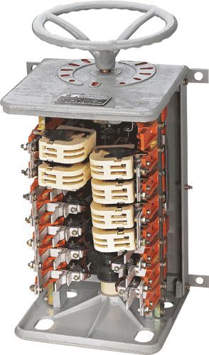
Structural Overview
The structure of the 100A and 160A controllers is the same, using cold extruded finger shaped copper contacts. The control circuit capacity and purpose vary (see circuit diagram for details).
The contact element of the controller is a rotating single break point structure, which is opened and closed by the changes in the concave and convex when the cam rotates. The positioning of each gear position is achieved through the cooperation of a positioning lever, a positioning ratchet, and a positioning spring.
The controller is made of protective type, with a steel plate outer cover, and the upper and lower bases are made of cast iron. The product structure is shown in Figure 1:
1. Cam drum. 2. Pillar 3, contact element 4, arc extinguishing cover 5, positioning spring 6, positioning lever 7, positioning ratchet
Appearance and installation of KT100/160J series AC cam controller
The external dimensions of the controller are shown in Figure 2 and Table 2
|
model |
KT-100J/1 |
KT-100、160J/2 |
KT-100、160J/3 |
KT-100、160J/5 |
KT-160J/1 |
|
Foot A B Inch C |
six hundred and forty |
seven hundred and fifteen |
five hundred and sixty |
seven hundred and fifteen |
six hundred and sixty-five |
|
five hundred and thirty-five |
six hundred and thirteen |
four hundred and fifty-seven |
six hundred and thirteen |
five hundred and sixty-one | |
|
four hundred and sixty-seven |
five hundred and forty-five |
three hundred and eighty-nine |
five hundred and forty-five |
four hundred and ninety-three | |
|
52.5Kg |
60.5Kg |
44.5Kg |
60.5Kg |
58Kg |
Table 2
1. The controller must be firmly installed on the bracket and cannot be suspended, that is, the lower base must be firmly attached to the ground or padded. There are four outlet holes on the lower base of the controller, and their dimensions are shown in Figure 1.
2. The basic wiring diagrams of each controller model are shown in Figures 3 to 7.
Usage and maintenance
After the controller is installed, it should be tested and operated normally before it can be put into use. Otherwise, the cause should be identified and the fault should be eliminated before testing.
The controller should be regularly inspected and maintained, and the melting spots on the contacts should be removed frequently with a file. Under the conditions of ensuring contact pressure and overtravel, the thickness of the contact after repair shall not be less than 4 millimeters. The contact pressure is 1.8-2.5 kilograms, which is equivalent to an overtravel of 3-5 millimeters at the contact and an opening distance of 8-13 millimeters.
The contact element equipped with an arc extinguishing cover is used for cutting resistors. If the arc is not large during use, the arc extinguishing cover can be used as a spare part for power contacts.
Regularly lubricate the rotating parts, replace damaged parts in a timely manner, and maintain tight connections.
The electrical connection must maintain sufficient pressure to prevent insulation damage caused by high temperature, especially paying attention to the pressure at the connection point of the soft connection on the insulation base.
Home|Quality Commitment|Ordering|Payment method|product delivery|support|Disclaimer|Contact Us
Copyright®2011 www.91way.com Copyright.
Phone:+86-21-66770508 +86-13916500500 Fax:+86-21-66108310
Email:91way@163.com Wechat:40606422
沪ICP备2021005791号 ![]() 沪公网安备31010702003255号
沪公网安备31010702003255号