
| Product name: | KTJ15A/B series AC cam controller | ||||||
| specification: |  |
||||||
| Category: | low-voltage electrical apparatus -- Master controller | ||||||
| Price: | factory price | ||||||
| Brand: | Shanghai | ||||||
| Place of Origin: | China | ||||||
| Available Quantity: | batch | ||||||
| delivery cycle: | Spot goods (or inquire by telephone) | ||||||
|
|||||||
|
Usage category |
Rated working current |
Connection conditions |
Breaking conditions |
Power on time (S) |
Interval time (S) |
Number of on-off cycles (10000 times) | ||||
|
L(A) |
U(V) |
COSФ |
L(A) |
U(V) |
COSФ | |||||
|
AC2 |
thirty-two sixty-three |
one hundred and twenty-eight two hundred and fifty-two |
four hundred and eighteen |
0.65 |
one hundred and twenty-eight two hundred and fifty-two |
four hundred and eighteen |
0.65 |
twenty-five |
5~10 |
Connection ≥ 0.05 Breaking ≤ 0.5 |
|
AC-11 |
2.6 |
28.6 |
four hundred and eighteen |
0.7 |
28.6 |
four hundred and eighteen |
0.7 |
fifty |
5~10 |
≥0.5 |
|
Usage category |
Rated working current |
Connection conditions |
Breaking conditions |
Number of on-off cycles (10000 times) | ||||
|
L(A) |
U(V) |
COSФ |
L(A) |
U(V) |
COSФ | |||
|
AC2 |
thirty-two sixty-three |
eighty one hundred and fifty-seven point five |
three hundred and eighty |
zero point six five |
eighty one hundred and fifty-seven point five |
three hundred and eighty |
zero point six five |
seven point five |
|
AC-11 |
two point six |
twenty-six |
three hundred and eighty |
zero point seven |
two point six |
three hundred and eighty |
zero point four |
sixty |
Allowable range of parameters in Tables 1 and 2: Current: ± 0.05% Voltage: (including recovery voltage) ± 5%
Power factor: ± 0.05
Appearance and installation dimensions
1. The external installation dimensions of the controller are shown in Figure 1 and Figure 2;
2. The wiring screws 10A and 32A of the contact element are M5, and 63A is M6.
|
model |
KTJ15A |
KTJ15B |
|
A |
two hundred and ten |
two hundred and ten |
|
B |
two hundred and thirty |
two hundred and thirty |
|
C |
one hundred and eighty |
two hundred and twenty |
|
L1 |
six hundred and fifty |
five hundred and twenty |
|
L2 |
seven hundred and thirty |
six hundred |
|
L3 |
eight hundred and fifty |
seven hundred and twenty |
Normal working conditions
Surrounding air temperature
5.1. The maximum ambient air temperature shall not exceed+40 ℃.
5.2. The lower limit of ambient air temperature shall not be lower than -5 ℃.
5.3. The average value within 24 hours shall not exceed+35 ℃.
Note: When used for -10 ℃ or -35 ℃, users should indicate it when placing an order.
5.4. Altitude
The installation location shall not exceed an altitude of 2000 meters.
5.5 Atmospheric conditions
The relative humidity of the atmosphere should not exceed 50% when the highest temperature in the surrounding area reaches+40 ℃. At lower temperatures, a higher relative humidity should be maintained. At the same time, when the average lowest temperature of the month is 25 ℃, the average maximum relative humidity of the wettest month is 90%, taking into account the condensation that occurs on the surface of the product due to temperature changes.
5.6 Pollution level
The pollution level of the controller is level 3.
5.7 Installation Category
The installation category of the controller is Class III.
Note: Any use beyond the above conditions should be resolved through a special ordering agreement between the supply and demand parties.
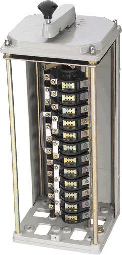
Structural Overview
The protection level of KTJ15A and B series AC cam controllers is IP30, and they are installed vertically.
The controller is divided into four parts: the control mechanism part, the cam and contact system part, and the housing part. The control handle is equipped with a self-locking device to avoid misoperation of the control mechanism due to crane vibration and accidental collision. When operating, simply press down the handle and open the zero position self-locking device to operate.
The mechanical transmission part is installed on the upper part of the box. The vertical operating handle is driven by a bevel gear to drive the camshaft, while the horizontal operating handle directly drives the camshaft to open and close the contact group according to the prescribed program. The camshafts of the controller are all installed vertically. The contact arrangement is single row except for KTJ15B-32/2, 63/2, 32/5, and 63/5 which are double row arrangements. Rolling bearings are used at each fulcrum of the transmission part to reduce friction.
The positioning ratchet is stamped from 3mm thick steel plate and undergoes appropriate heat treatment to obtain good wear resistance. The controller has five gear positions. Within the range of five gears on each side, the number of gears can be freely selected. The positioning ratchet spring force can be adjusted, so that the ratchet spring force can be adjusted according to the specific situation, under the premise of clear gear classification, to make the handle operating force within the allowable range.
The cam is formed by pressing black phenolic plastic, and its structure is through the ventricle, ensuring accurate assembly position.
The contact group structure is a rotating double break point. The installation dimensions of the 32A and 63A contact groups are the same, so they are commonly used for installing support rods. The machine base is made of die cast aluminum parts, and the upper panel is formed by stretching steel plates. The machine base and panel are connected by four pillars, which have the characteristics of light weight and good rigidity. The front and rear covers can be easily removed for installation, wiring, and maintenance.
Usage and maintenance
7.1. The controller should be fixed with installation screws. Insert the handle rod into the operating wheel hole of the vertical handle and push it down firmly. The positioning lock will automatically lock, and then you can operate it.
According to the requirements of the electrical schematic diagram, operate the controller step by step and observe whether the opening and closing of the contacts match the contact opening and closing program in the wiring diagram.
Before powering on, it is necessary to check whether the wiring of the electrical system related to the motor and resistor is correct and whether the grounding is reliable.
7.4 After power on, carefully check the operation of the motor according to the corresponding controller. If there is a difference, immediately cut off the power and wait for the cause to be identified before continuing to power on.
7.5 The controller should be regularly inspected and maintained according to the following requirements:
7.5.1 All screw connections must be tightened, especially the contact wiring screws;
7.5.2 The friction part should be regularly lubricated;
7.5.3 The working surface of the contact should have no obvious melting spots, and the melted parts can be carefully repaired with a fine file. The use of sandpaper is not allowed.
Damaged parts should be replaced in a timely manner.
Home|Quality Commitment|Ordering|Payment method|product delivery|support|Disclaimer|Contact Us
Copyright®2011 www.91way.com Copyright.
Phone:+86-21-66770508 +86-13916500500 Fax:+86-21-66108310
Email:91way@163.com Wechat:40606422
沪ICP备2021005791号 ![]() 沪公网安备31010702003255号
沪公网安备31010702003255号