
| Product name: | EKL-3.1 type fault indicator | ||||||
| specification: |  |
||||||
| Category: | High voltage electrical appliances -- fault indicator | ||||||
| Price: | factory price | ||||||
| Brand: | |||||||
| Place of Origin: | China | ||||||
| Available Quantity: | batch | ||||||
| delivery cycle: | Spot goods (or inquire by telephone) | ||||||
|
|||||||
The EKL-3.1 fault indicator is an assembled component Used for detecting ground faults and short circuit faults It operates in a star shaped network with only one current input port and medium voltage The minimum value of grounding fault current must be 10A (resistance grounding or fixed grounding grid) The EKL-3.1 fault indicator must be installed on each branch of the network to indicate
a) Short circuit fault detection: Each of the three wires is indicated by an indicator light
b) Ground fault detection: There is a total of one indicator light
c) Remote signal: Remote signals can be used to indicate short circuits and ground faults indiscriminately, or remote signals can be used to differentiate between ground faults
Indicate short circuit and ground fault
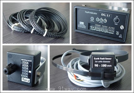
Design the composition of grounding and short-circuit fault indicators: 3 short-circuit sensors, 1 grounding fault sensor, 1 reading device, and connecting wire or fiber optic cable reading device are installed in a plastic housing with devices for measuring current and setting fault indication time limits
A ground fault is indicated by a flashing indicator light, while a short circuit fault is indicated by one indicator light on each of the three wires The indicator shell has an indicator function detection key and an indicator status restoration key. The sensor is also equipped with a plastic casing, and the coil inside the casing is used to sense the current caused by short circuit or grounding. Sensors can be connected to wires or optical cables according to assembly requirements. The fully cast plastic casing meets the IP65 protection standard
Zero voltage data transmission between short-circuit/grounding sensors and reading devices can be achieved through optical cables. The optical cable is made of PMMA material and has a maximum length of 10 meters
After setting the fault current value, once the current value measured by the coil in the sensor is greater than the set fault value, the real-time current pulse is transmitted to the indicator and read, and the indicator light will also send a fault signal to the outside accordingly There is also a minimum pulse delay setting device inside the indicator, which is used to measure the delay of the current pulse captured by the sensor and compare it with the set value, thereby avoiding erroneous indications caused by the instantaneous peak current being too high when the power grid is energized or in other situations Each device can set up to four minimum pulse delays. The specific setting values have been set according to the buyer's wishes before leaving the factory Device reset 1. It can be controlled by a timer, and after the set indication duration ends, it will automatically return to the non indication state. Each device can be set with four indicator durations, ranging from 0.5 hours to 40 hours. 2. Manually turn back the button. 3. The power grid will automatically return to its original position after being powered on
The installation indicator is installed outside the high voltage zone. Short circuit sensors can be installed on high-voltage wires with or without shielding. The ground fault sensor must be installed around three wire cores to ensure that the total current of the three wires is measured When installing the sensor, its frame can be opened The short-circuit sensor is connected to the indicator through an optical cable, and the grounding sensor is connected through a wire
Overview of Technical Data
Short circuit fault current definition value setting: 100-1500 A
Grounding fault current definition value setting: 100--1500 A10 A --200 A*
Error range:+/-10%
Working environment temperature: -18 degrees Celsius to+60 degrees Celsius
indicator
Indication time setting: Minimum pulse delay: between 0.5 hours and 40 hours (4 values) between 20 milliseconds and 500 milliseconds (4 values)
Indicator required current: standby state requires 5-10 A, startup indicator requires 60A
Power indicator battery requirements: -230V AC (rechargeable batteries are also available) -9V to 110V DC - lithium battery
Remote indication: Shell size: Grounding and short circuit: Maximum 230V AC/50 to 150 watts
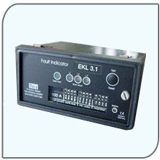
Surface installation of indicator housing 76x140x42mm (length, height, width)
Embedded installation 96x48x63mm (length, height, width)
Sensor housing short circuit 38x38x26mm (length, height, width) grounded 38x38x26mm (length, height, width)
EKL-3.1 type fault indicator
Home|Quality Commitment|Ordering|Payment method|product delivery|support|Disclaimer|Contact Us
Copyright®2011 www.91way.com Copyright.
Phone:+86-21-66770508 +86-13916500500 Fax:+86-21-66108310
Email:91way@163.com Wechat:40606422
沪ICP备2021005791号 ![]() 沪公网安备31010702003255号
沪公网安备31010702003255号