
| Product name: | ZN73 series indoor AC high-voltage vacuum circuit breaker | ||||||
| specification: |  |
||||||
| Category: | High voltage electrical appliances -- Indoor vacuum circuit breaker | ||||||
| Price: | factory price | ||||||
| Brand: | |||||||
| Place of Origin: | China | ||||||
| Available Quantity: | batch | ||||||
| delivery cycle: | Spot goods (or inquire by telephone) | ||||||
|
|||||||
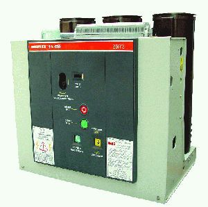
The ZN73-12 indoor high-voltage vacuum circuit breaker (hereinafter referred to as the circuit breaker) is a three-phase AC 50Hz indoor device with a rated voltage of 12kV. It is suitable for switching various types of loads and frequent operations, and can be used for the protection and control of industrial and mining, enterprise, power plant equipment, and substation electrical facilities.
The circuit breaker complies with the 1984 and JB3855 standards.
Normal working conditions
1. Surrounding air temperature: upper limit not exceeding+40 ℃; The lower limit shall not be lower than -10 ℃.
2. Altitude: The altitude shall not exceed 1000m.
3. Humidity: Relative humidity: Daily average not exceeding 95%, monthly average not exceeding 90%; Saturated vapor pressure: The daily average value shall not exceed 2.2 × 10⁻³Mpa, and the monthly average value shall not exceed 1.8 × 10⁻³Mpa. During periods of high humidity, condensation may occur when the temperature drops sharply.
4. Seismic intensity: The seismic intensity shall not exceed 8 degrees.
5. The surrounding air should not be significantly polluted by corrosive or flammable gases, water vapor, etc.
6. There is no frequent severe vibration in the place of use.
Note: If users need circuit breakers that exceed the normal usage conditions mentioned above, they can negotiate with our company to customize them.
Meaning and Classification of ZN73 Series Indoor AC High Voltage Vacuum Circuit Breaker Models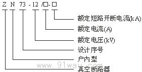
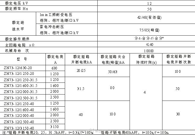
Main technical parameters of ZN73 series indoor AC high-voltage vacuum circuit breaker
The mechanical characteristic parameters of the circuit breaker are shown in Table 2.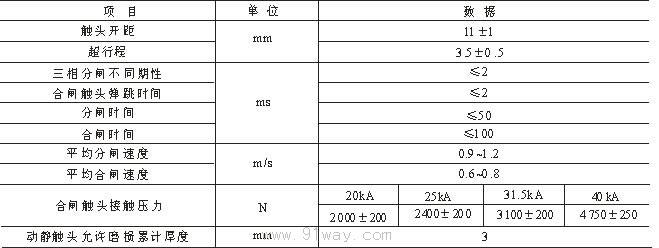
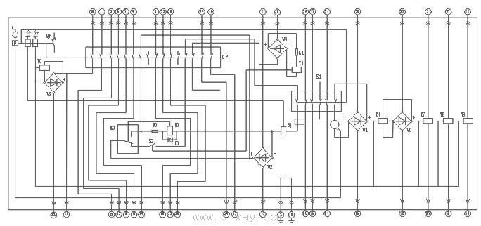
KO internal anti bounce relay Y1 locking electromagnet (optional) DO diode
HQ closing release R0, R1 current limiting resistor TQ opening release
Y4- Low voltage release (optional) M-energy storage motor with spring operated mechanism
Y7~Y9- Indirect overcurrent release (optional) S2- Auxiliary switch for locking electromagnet (optional) V0~V4- Rectification element S1- Micro switch for energy storage
P-Manual Operating Mechanism QF - Auxiliary Switch for Main Contact of Circuit Breaker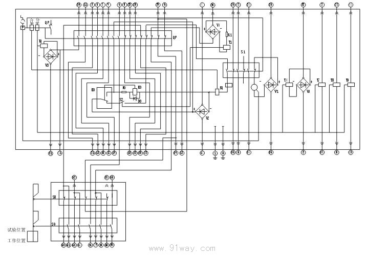
Internal anti bounce relay HQ closing release of KO organization
DO diode TQ circuit breaker
R0, R1- current limiting resistor M-spring operated energy storage motor
Y4- Low voltage release (optional) S9- Auxiliary switch for working position
Y7~Y9- Indirect overcurrent release (optional) S8- Auxiliary switch for test position
V0~V4- rectifier component S2- auxiliary switch for locking electromagnet (optional)
P-Manual operating mechanism S1 Micro switch for energy storage
Y1 locking electromagnet (optional) QF auxiliary switch for circuit breaker main contact
Figure 2 Internal wiring diagram of handcart circuit breaker
Appearance and installation dimensions
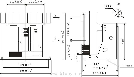
Note: The numbers in parentheses indicate the size of circuit breakers with a rated current greater than 1600A.
Figure 1: Outline, Installation, and Dimensional Diagram of Fixed Circuit Breaker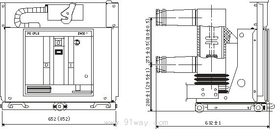
Note: 1. The travel distance of the handcart in the cabinet is 200mm;
2. The numbers in parentheses indicate the external dimensions of circuit breakers with a rated current greater than or equal to 1600A.
Home|Quality Commitment|Ordering|Payment method|product delivery|support|Disclaimer|Contact Us
Copyright®2011 www.91way.com Copyright.
Phone:+86-21-66770508 +86-13916500500 Fax:+86-21-66108310
Email:91way@163.com Wechat:40606422
沪ICP备2021005791号 ![]() 沪公网安备31010702003255号
沪公网安备31010702003255号