
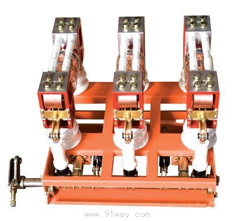
| Product name: | ZN28G-12 series indoor high-voltage vacuum circuit breaker | ||||||
| specification: |  |
||||||
| Category: | High voltage electrical appliances -- Indoor vacuum circuit breaker | ||||||
| Price: | factory price | ||||||
| Brand: | |||||||
| Place of Origin: | China | ||||||
| Available Quantity: | batch | ||||||
| delivery cycle: | Spot goods (or inquire by telephone) | ||||||
|
|||||||
Product Overview
1. The ZN28A-12 series indoor AC high-voltage vacuum circuit breaker is mainly used in fixed switchgear, as a protection and control component for electrical equipment in industrial and mining enterprises, power plants, and substations, and is suitable for frequent operation in places.
2. ZN28G-12 is a derivative model of ZN28A-12, which adopts an integrated layout of circuit breaker and operating mechanism in front and back, making installation and use more convenient and stable. It can be directly configured with CD17 electromagnetic mechanism and CT19 spring mechanism.
3. ZN28C-12 is a derivative model of ZN28A-12, which has a handcart structure and can be assembled with KYN1-12 handcart, KYN18-12 handcart, JYN2-12 handcart, JYN3-12 handcart. The circuit breaker and operating mechanism are arranged vertically, and can be configured with CD17 electromagnetic mechanism or CT19 spring mechanism.
ZN28G-12 series indoor high-voltage vacuum circuit breaker models and their meanings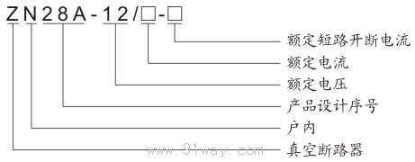
Environmental conditions for use
1. Surrounding air temperature: upper limit+40 ℃, lower limit -10 ℃ (storage and transportation allowed at -30 ℃);
2. Relative humidity: daily average not exceeding 95%; Monthly average not exceeding 90%;
Daily average saturated vapor pressure: The daily average is not greater than 2.2KPa, and the monthly average saturated vapor pressure is not greater than 1.8kPa,
3. Altitude: not exceeding 2000m (2500m is considered high prototype);
4. Seismic intensity: not exceeding 8 degrees;
5. A place without fire, explosion hazard, serious pollution, chemical corrosion, and severe vibration.
Main technical parameters of ZN28G-12 series indoor high-voltage vacuum circuit breaker
| serial number | project | unit | Parameters | ||
| ZN28A-12/630、1000、1250-20 | ZN28A-12/630、1250、1600-25 | ZN28A-12/630、1250、2500-31.5 | |||
| one | rated voltage | kV | twelve | twelve | twelve |
| two | rated current | A | 630 1000 1250 | 630 1250 1600 | 1250 1600 2000 2500 |
| three | Rated short-circuit breaking current | kA | twenty | twenty-five | thirty-one point five |
| four | Rated short-circuit closing current (peak) | kA | fifty | sixty-three | eighty |
| five | Rated withstand current (peak) | kA | fifty | sixty-three | eighty |
| six | Rated short-time withstand current | kA | twenty | twenty-five | thirty-one point five |
| seven | Rated short-time duration | s | four | four | four |
| eight | Rated short-circuit breaking current breaking times | time | fifty | fifty | fifty |
| nine | Rated operating sequence | Min-0.3s HeFen-180s HeFen | |||
| ten | 1-minute power frequency withstand voltage (effective value) | kV | forty-two | forty-two | forty-two |
| eleven | Lightning impulse withstand voltage | seventy-five | seventy-five | seventy-five | |
| twelve | mechanical life | time | ten thousand | ten thousand | ten thousand |
| thirteen | Contact opening distance | mm | 11±1 | 11±1 | 11±1 |
| fourteen | Contact itinerary | mm | 4±1 | 4±1 | 4±1 |
| fifteen | Synchronization of three-phase opening and closing | ms | ≤2 | ≤2 | ≤2 |
| sixteen | Bouncing time of closing contact | ms | ≤2 | ≤2 | ≤2 |
| seventeen | Center distance between poles | mm | 250±5 | 250±5 | 250±5 |
| eighteen | Average opening speed (before contact with oil buffer) | m/s | 0.7~1.3 | 0.7~1.3 | 0.9~1.3 |
| nineteen | Average closing speed | m/s | 0.4~0.8 | 0.4~0.8 | 0.4~0.8 |
| twenty | Accumulated allowable wear thickness of dynamic and static contacts | mm | three | three | three |
Home|Quality Commitment|Ordering|Payment method|product delivery|support|Disclaimer|Contact Us
Copyright®2011 www.91way.com Copyright.
Phone:+86-21-66770508 +86-13916500500 Fax:+86-21-66108310
Email:91way@163.com Wechat:40606422
沪ICP备2021005791号 ![]() 沪公网安备31010702003255号
沪公网安备31010702003255号